

Recommended News
contact us
Tel: +86-21-56031255
Mobile: +86-18930968947
E-mail:fcj@muhong.cn
muhongjidian@vip.163.com
wechat: +86-18930968947
whatsapp: +86-18930968947
skype: muhongjoseph
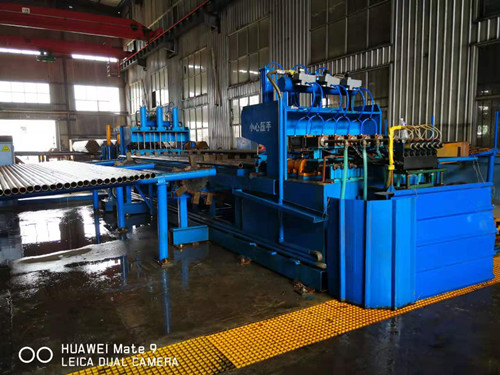
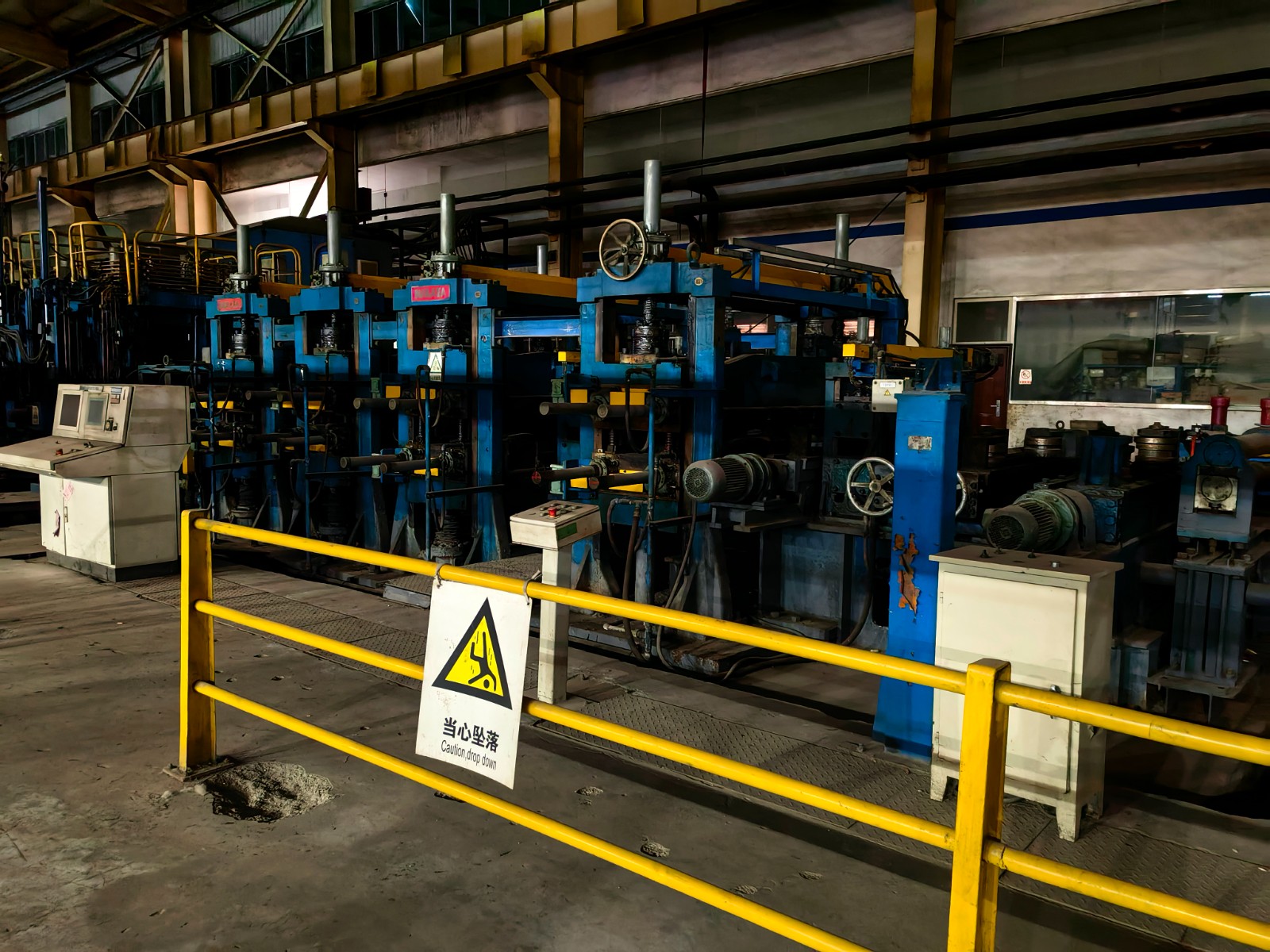
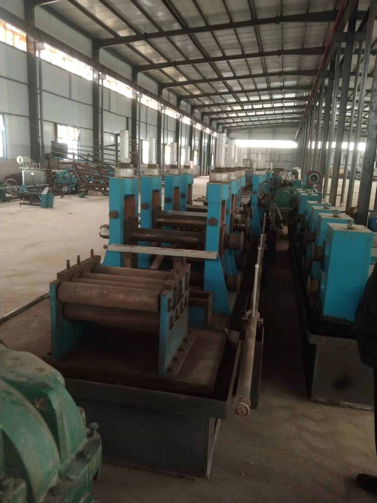
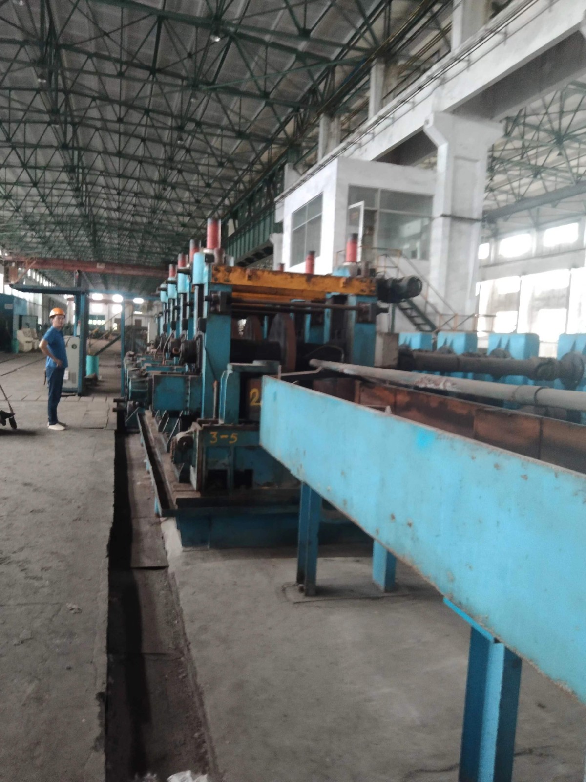
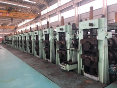
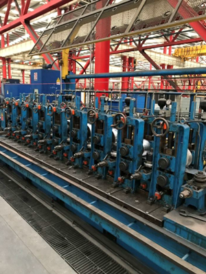
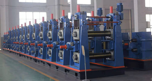
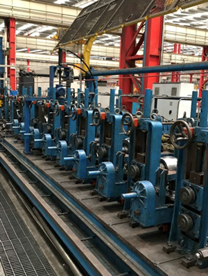
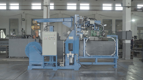
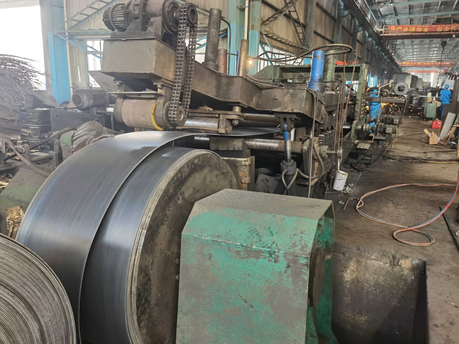
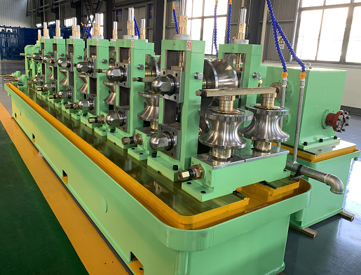
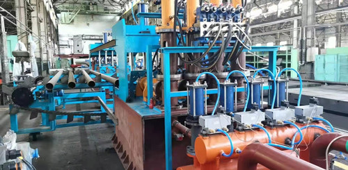
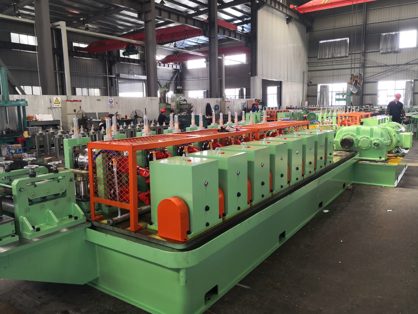
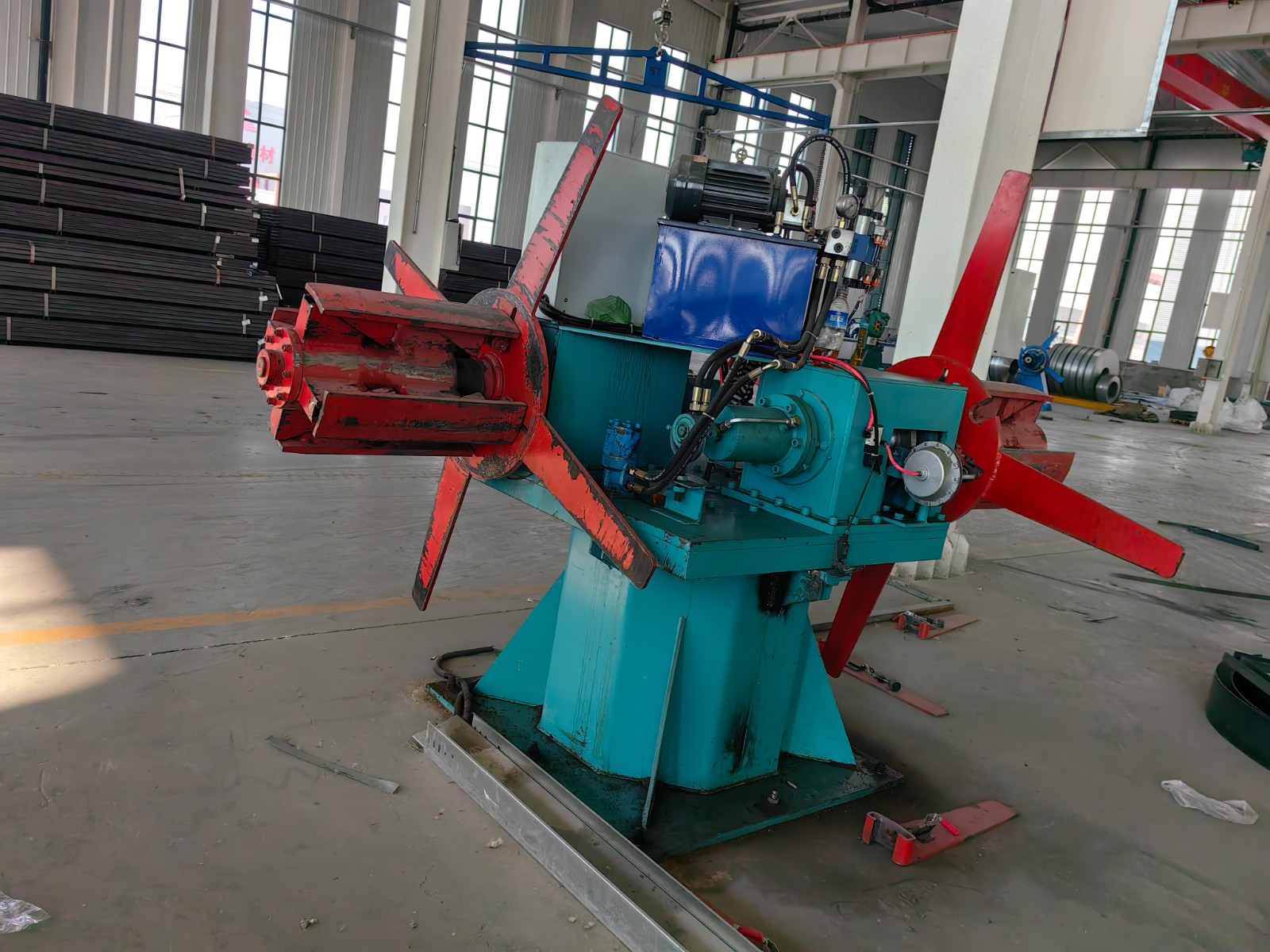
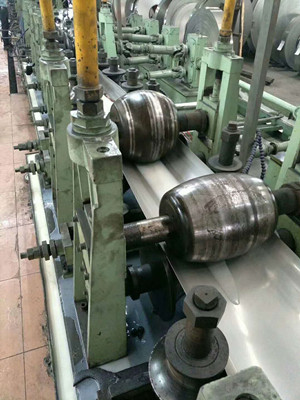
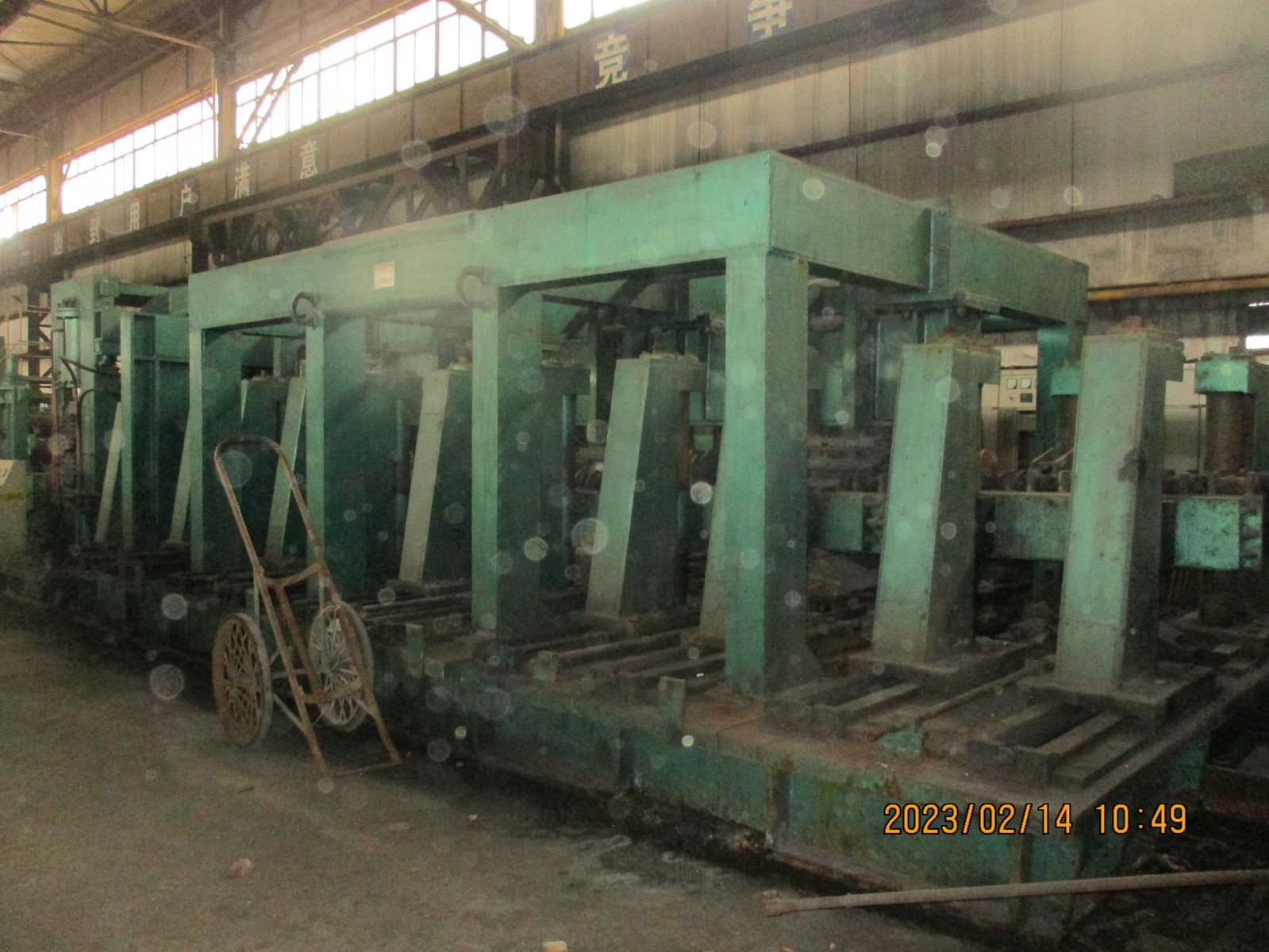
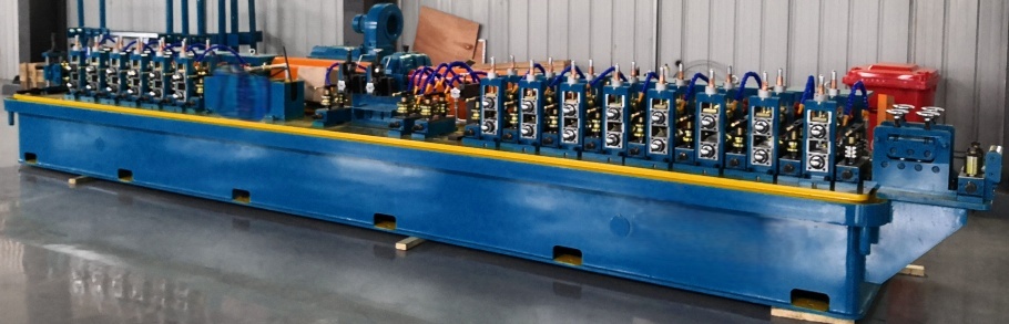
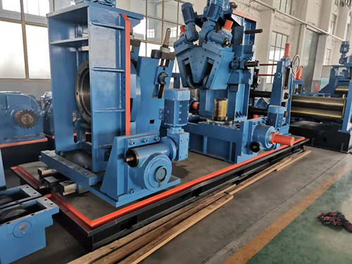
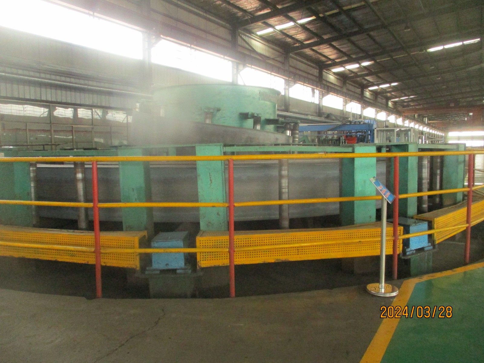
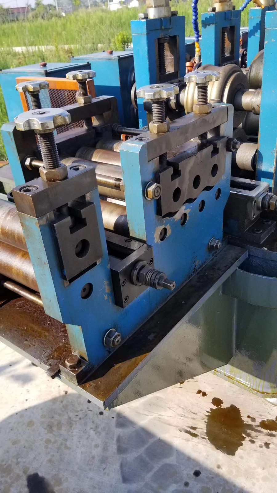
ERW Tube Mill

No. 196 6 station tube hydro testing machine
The written time is August 18,2021.- product description
- Technical Parameters
The length of steel pipe is 6015 ± 10mm.Test pressure: 2-7mpa.
1.Product outline and technical parameters
1.1Production beat Description:
model | Steel pipe specification (mm) | Workstation | Sealing mode | Capacity (piece / hour) | Quantity (set) |
60-6 | φ21~60 | 6 | End seal | 600 | 1 |
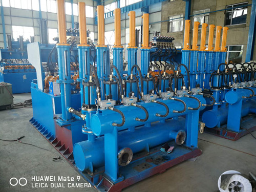
1.2Main configuration table of hydraulic press
Specifications | Pressing outer diameter | Sprocket transfer | Hydraulic station | Pipeline pump | Configured total power |
60-6 | 21、26、32、42、60 | Frequency conversion 4.0kw | Double pump 22kw | Double pump 22kw | 90KW |
1.3Working process:
Unpacking and storage bench (4m long, supporting and discharging) - inclined bench storage - pushing (chip blowing) - reclaiming and feeding - clamping - pipe jacking - pressurization and pressure maintaining - recovery - Loosening - transverse movement - water control - blanking bench - waste pipe sorting - packaging (equipped with mechanical hexagonal stacker and manual binding belt).
1.3.1Unpacking: after the packaged steel pipe is opened on the unpacking frame, the outer side of the support frame is raised to form an inclined plane, and the pipe is placed on the feeding cooling bed.The oil cylinder controls the outer support and manual switch control.
1.3.2Pipe arrangement: the cooling bed is designed to slide naturally at an angle of 3.5-5 degrees. If the steel pipe is not tight, manual intervention is required.
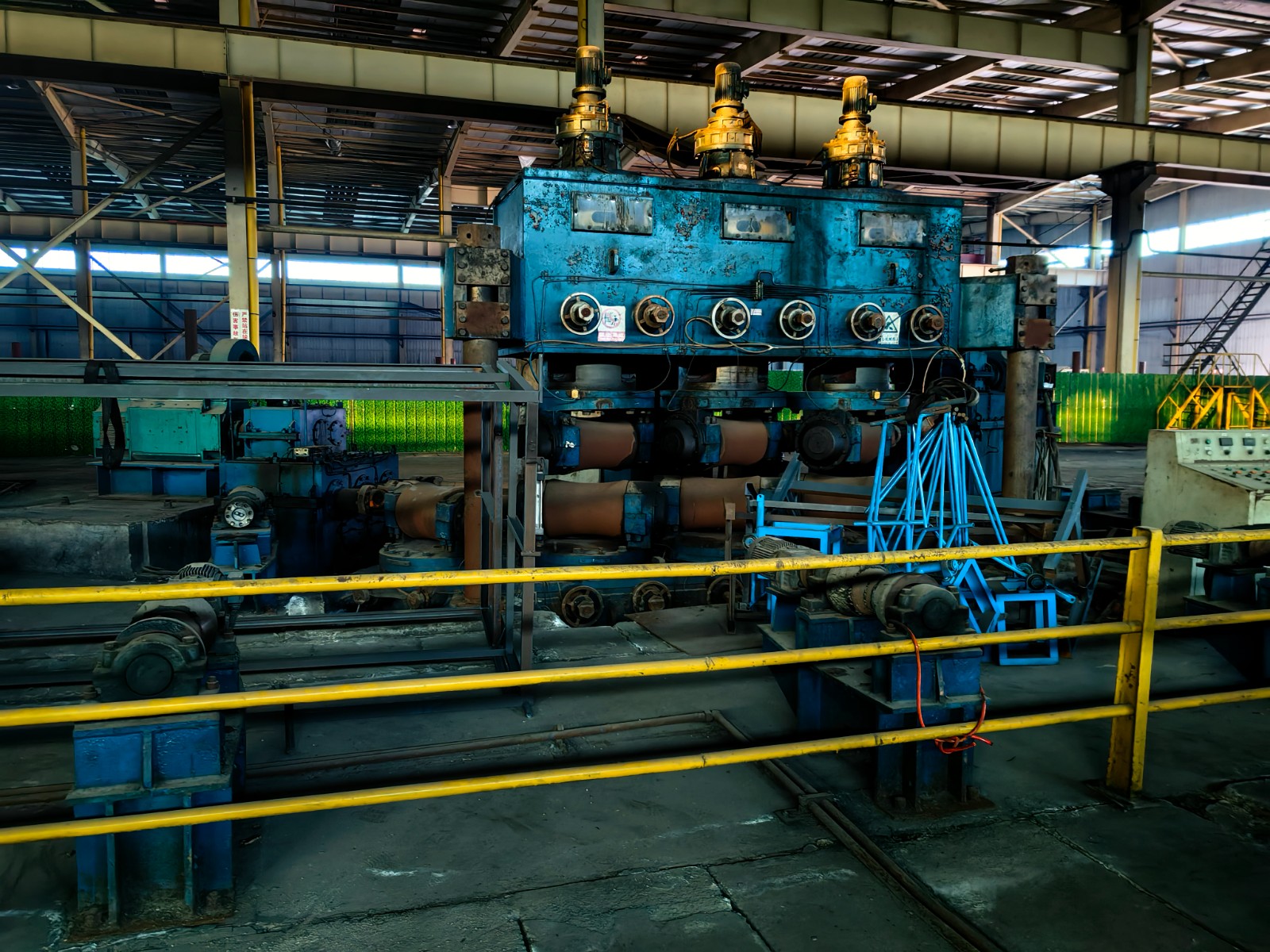
1.3.3Branch transfer: the main machine system of the hydraulic press adopts the form of automatic chain branch to realize branch and transfer. One process position is transferred at a time. For example, 6 pipes are transferred at a time at station 6 and 2 pipes are transferred at a time at station 2.
1.3.4Pushing: during the transfer process, the rolling is continuously pushed, and the pushing roller operates time-sharing to ensure that the steel pipe is pushed in place, so as to avoid damaging the steel pipe by pushing friction.Here, a chip blowing port can be added at the push up baffle to realize dynamic flushing and chip blowing.
1.3.5Clamping: the hydraulic press adopts upper clamping and lower clamping cooperation for small pipes below 42, with a total of 4 to 4 clamping to prevent steel pipe bending.Universal clamping structure is adopted for clamping, and the clamping shoe does not need to be replaced to simplify the operation.48-219 adopts single side clamping mode, without intermediate clamping, and the field of vision is wider.
1.3.6Seal: 60-6 and 114-4 adopt end seal and 219-2 adopt diameter seal.
1.3.7Water injection: large lift pipeline water pump is used for water injection, with short and sufficient water injection time to improve the exhaust capacity.Each steel pipe is injected with water independently, with independent valve and independent plugging, and the high-pressure water chamber of each station is completely independent.
1.3.8Pressurization and pressure maintaining: after water injection, block the water outlet, close the water inlet, and start pressurization and pressure maintaining of independent oil cylinder.The pressurization and pressure maintaining are controlled by a three position hydraulic solenoid valve. After the pressurization is completed, the solenoid valve is in the power-off locking position, no pressurization or pressure reduction, and enters the pressure maintaining oil-water balance stage.
1.3.9Recovery: after pressurization and pressure maintaining, depressurize first to prevent high-pressure water from splashing, and then open the outlet for blocking to connect the water flow in the pipe with the atmosphere and completely release the pressure.Then withdraw the jacking pipe and loosen the clamp.
1.3.10Transfer: after the pressing process is completed, the transfer starts. The transfer is closely connected with the feeding and discharging cooling bed. The pressed steel pipes slide naturally to the cooling bed. At the same time, a batch of new pipes are sent to the pressing station.The cooling bed is designed for 5 degree landslide.
1.3.11Hexagonal packing frame: it has the results of pushing, packing, material belt installation, etc.If packing is not required, a sling can be placed on the material frame for convenient lifting.The width of the cladding frame can be adjusted according to the steel pipe specification.Six cylinders are used for manual intervention.Then manually weld the packing belt.
2. Technical features of HDM series hydraulic testing machine:
2.1High pressurization accuracy: high resolution pressure sensor is adopted to monitor the pressurization process, and real-time display and record the pressurization value, pressurization curve and pipe leakage indication.In case of pipe leakage, the alarm can realize semi-automatic re inspection to avoid mistakenly believing that there is a leakage point in the steel pipe due to equipment reasons.
2.2Many observation methods: equipped with shockproof pressure gauge.Manual observation, pressure gauge indication, large screen display of pressure curve, large screen display of pressure value, touch screen pressure value and pipe leakage alarm, etc.
2.3Simple re inspection: in case of pipe leakage, manual intervention can realize semi-automatic re inspection, and re inspection can be repeated many times.
2.4The end seal is not bent and has no dead angle: for the steel rod with small diameter below 42, four clamping devices are used to ensure that the pressure is not bent.The end seal mode is adopted for the pressure seal below 89 to ensure that there is no dead angle.
2.5Diameter seal high pressure seal: 140-219 adopts diameter seal to seal the pipe orifice. We adopt U-shaped double chamber high pressure diameter seal. Before water injection, pressurize the pressure chamber of the diameter seal ring to the sealing pressure to realize sealing.The utility model has the advantages that the sealing ring has no contact with the steel pipe during pipe jacking, the sealing ring will not be damaged due to friction, and the service life of the radial sealing ring will be improved.
2.6Features of pressure test head: the pressure test head is easy to install and disassemble, and the sealing ring is easy to replace.The seal is designed according to the sealing form of oil pump to reduce the probability of leakage and there is almost no water leakage point.
2.7Low use cost: the main components involved in water of the system are made of stainless steel, valve flange and sealing flange.The end seal gasket adopts U-shaped bushing inlay structure to improve the service life of the seal ring.
2.8Avoid iron scraps scratching the sealing ring: the bushing of the water outlet chamber of the jacking pipe adopts the form of filter screen to prevent large iron scraps from entering the water outlet chamber and scratching the sealing ring.Small iron filings will not stay through the vertical blocking chamber.Greatly improve the service life of the sealing ring.
2.9Orderly water flow: when withdrawing and jacking the pipe, the water flow in the pipe is on the workbench, and there is a fixed water channel flowing to the ditch.
2.10Compact structure: the water inlet pipe jacking workbench and booster workbench are made into an integrated structure, and the hydraulic solenoid valve and pneumatic solenoid valve of the water outlet workbench are arranged near the cylinder block.All internal pipelines are installed before leaving the factory, which greatly reduces the construction time and workload of on-site installation.Standardized design and installation, with aesthetic feeling.
2.11Wide field of vision: steel pipes with an outer diameter of more than 48 can only be clamped down, which has a wide field of vision and is convenient for observation.
3. Technical requirements and indicators of main engine
3.1 60-6Technical requirements and indexes of hydraulic testing machine:
3.1.1Number of work positions: 6 stations.
3.1.2Test pressure: 3-7mpa(30-70 kg).
3.1.3Pressure test pipe specifications: 21, 26, 32, 42, 48, 60, six specifications, equipped with six kinds of molds, bushings and gaskets.
3.1.4Production rhythm (calculated according to 5 MPa pressure holding for 5 seconds), 10-12 pieces / min, 600 pieces / hour.
3.1.5Sealing form: end seal.
4. Itemized Description:
4.1Electric control system:
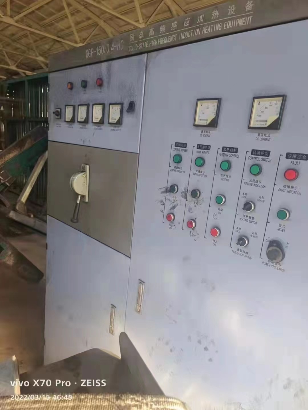
4.1.1Control cabinet
4.1.1The operation mode is divided into three modes: manual, semi-automatic and automatic pressurization. In case of pipe leakage alarm, semi-automatic recheck can be selected to confirm that it is pipe leakage rather than equipment sealing problem.
4.1.1.2The system includes one main cabinet, one operation cabinet and one large monitoring screen (60 Inch display).
4.1.2 PLC controller: Omron product, which realizes the detection and control of the whole system (switching value, analog value and counting, etc.).
4.1.3Computer: famous brand industrial control computer is selected, which has the functions of man-machine interface, original data storage, system parameter setting, independent pressure test curve display, operation status display, counting and printing.It mainly includes:
4.1.3.1Brief screen of host, including main parameters of host and system;
4.1.3.2The pressure test parameter screen can be directly used to set the steel pipe specification, batch number, length, wall thickness, steel grade, test pressure, pressure holding time, water filling, exhaust time, counting, etc;
4.1.3.3It can form production and quality reports and store the pressure test curve of single branch pipe.
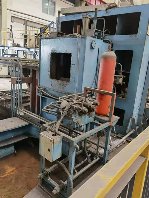
4.2Pneumatic system:
A 0.5-1m3 buffer tank is set at the air supply inlet.
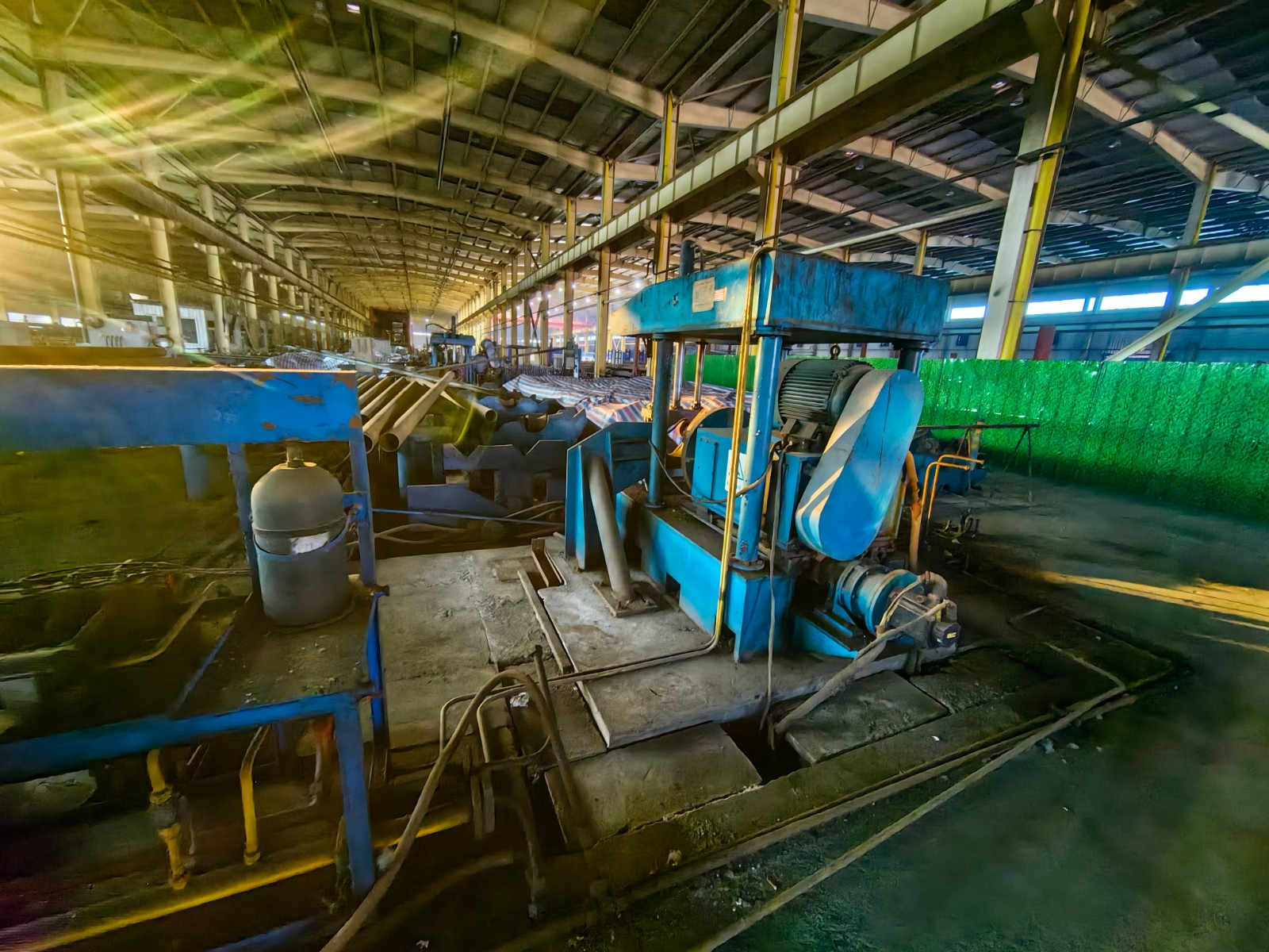
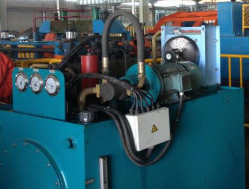
4.3Hydraulic system:
4.3.1It is composed of one hydraulic station and three valve stations. The hydraulic station is composed of motor, oil pump, oil tank, oil circuit block, pressure gauge, cooler, oil level gauge, oil filter, overflow valve, etc.
4.3.2The flow shall not be less than 100L / min, the working pressure shall be 12MPa (maximum 16mmpa), and the oil tank capacity shall be more than 1.5m3.
4.4Emulsion system: the emulsion after pressure test flows back to the underground water tank by itself, and the iron oxide scale is precipitated in the emulsion ditch and sedimentation pit beside the machine.This part shall be implemented by Party A.
4.5Safety protection: both sides of the host are against the steel plate of the frame body, and there is no protection above and on both sides.
5. Select brands of purchased parts and standard parts:
5.1AC motor: hydraulic motor, water pump motor, unpacking branch motor and transfer motor all adopt Hengshui Mengniu brand motor.
5.2Servo motor: the automatic lifting frame servo motor adopts the original controller and motor from Yaskawa, Japan.
5.3Variable frequency governor: the original governor of Yaskawa shall be used for the transfer of variable frequency governor.
5.4Hydraulic system: Shanxi Yuci products are used for hydraulic station and oil cylinder, and Beijing Huade products are used for hydraulic solenoid valve.
5.5Pneumatic components: Beijing Zhaoqing Fangda equivalent quality products.
5.6Electrical components: Schneider products are used.PLC adopts Omron expandable network communication products.
5.7Reducer: Chinese brand.
5.8Bearing: P6 product of Harbin Bearing Factory is adopted.
6. Supply details:
6.1Supply details of single system of hydraulic press host:
No | name | 60-6 | remarks |
1 | Electric control system and console | 1 | |
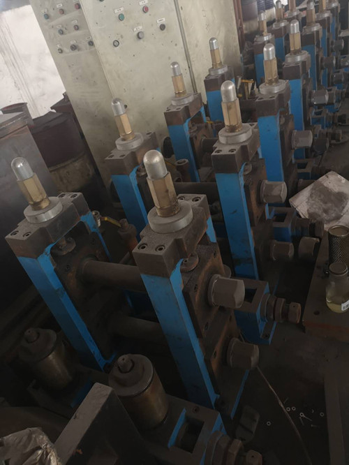
2 | Valve cylinder | 6 | |
3 | Plugging cylinder | 6 | |
4 | Booster cylinder | 6 | |
5 | Pipe jacking cylinder | 12 | |
6 | Hydraulic valve group | 3 | |
7 | Clamping cylinder | 8 | |
8 | Pneumatic solenoid valve | 13 | |
9 | Double pump hydraulic station | 1 | |
10 | Large head and large flow water pump | 2 | |
11 | Pressure sensor | 6 | Key spare parts |
12 | Shockproof oil pressure gauge | 6 | |
13 | Number of transfer sprockets | 6 | |
14 | Number of transfer chains | 3 | |
15 | Transfer motor | 1 | |
16 | Pipe jacking box | 2 | |
17 | Water storage tank | 1 | |
18 | Gas separation tank | 3 | |
19 | Complete set of pressure test head (including stainless steel bushing and gasket), (including equipment installation part). | 72 | The jacking gasket is a vulnerable part |
20 | Proximity switch, speed measurement transfer in place. | 1 | |
21 | Solenoid valve spare parts shall be provided outside the equipment. | 2 | |
22 | Pressure sensors shall be provided outside the equipment. | 2 | |
23 |
6.2Details of auxiliary system:
No | Equipment name | quantity | remarks |
1 | 60-6Unpacking bench | 1 | Support tilt, forward feed drive, 3M long |
2 | 60-6Feeding and discharging buffer bench, | 1 | Including feeding pushing device and temporary storage bench |
3 | 60-6Packing frame. | 1 | Including air cylinder, mechanical stacker, adjustable six corner material rack (with sling rack). |
7. Party A shall be responsible for following items
7.1 114The following steel pipes need to be straightened, and the bending degree of the steel pipe is less than 1mm / m.The ends of steel pipes below 89 need flat ends, and 140-219 steel pipes need flat ends or flat outer chamfering.
7.2 Provide the power supply required on site to the switchgear.
7.3 Provide air supply to three knockout tank inlet points.
7.4 Seamless pipe and connection buckle between hydraulic station and three valve groups.
7.5 Provide production and installation personnel to cooperate with equipment installation and wiring.
7.6 Provide required water tank, water pump to water tank and water pump to outlet pipe pipeline and installation construction.
7.7Provide equipment foundation, materials and construction required for equipment improvement, operation console, table 800-950 higher than the ground, display installation, etc.
7.8 Provide personnel cooperation and index identification required for equipment acceptance.It is required to accept the equipment within 30 days after commissioning. If the equipment is not accepted or no objection is raised within 30 days, the product is qualified and enters the warranty period.
8. Contents and service commitments provided by the supplier:
8.1Provide the overall framework content and products of the equipment in the contract.
8.2Provide connecting wires between equipment and guide installation and commissioning.
8.3Provide mechanical equipment installation drawings and vulnerable parts drawings.
8.4Provide equipment operation and maintenance instructions and a full set of circuit drawings, gas circuit drawings, hydraulic drawings and overall layout drawings.
8.5Provide vulnerable parts and accessories that meet the needs of equipment during test and inspection.
8.6Within the warranty period, repair the faults not caused by improper operation and replace the damaged parts free of charge.
9. Acceptance criteria:Product executive standard: GB / t3091-2015
9.1After the goods arrive at the designated place in Party A's yard, Party A shall conduct preliminary acceptance of the quantity and surface of equipment and articles according to the number of work positions given in the contract.
9.2During equipment installation, the rationality of equipment installation shall be inspected and accepted according to the basic drawings and technical requirements.
9.3Two specifications of equipment commissioning test shall be inspected according to the maximum pressure and minimum pressure. Pressurization and pressure holding test shall be carried out for 5-30 seconds.If the pressure curve and value are correct, the indication of the pressure gauge is stable, and the touch screen display is normal, it is qualified.
9.4If the pressure on the leaking pipe shows leakage or failure to maintain the pressure, it is qualified.
9.5Conduct continuous pressure test at the specified speed,
Test for 10 minutes, estimate the pressure quantity in 1 hour, and it is qualified if it meets the speed requirements.
The above five items are the basis for product inspection.
If you want to quote or further information on this product, please fill out the form below.
- product name
- Your Name
- phone number
- E-mai *
- Message content *
-
Security Code
*
Previous:No.197 New MH50 high frequency welded pipe mill unit
Next:No.195 auto strapping machine for steel tube and steel pipe or steel coil
-
 2018 Nanyang OD12.7-50mm ERW tubemill
-
 NAKATA 2006 used OD355mm ERW tubemill
-
 OD45-105mm ERW Tubemill
-
 200×200×14mm direct forming tubemill
-
 CR No.61 Used 1600mm Cold Bending Roll Forming Machine
-
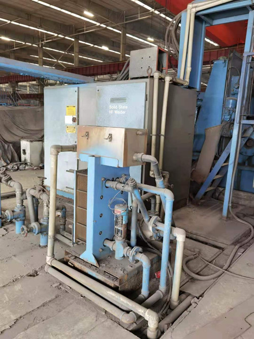
 ET No.111 Used OTO mills Solid state HF Welder Stainless steel tube mill
-
 No.198 New OD 377 tubemill
-
 used 40×40mm~100×100mm ERW tubemill
-
 ET No.110 Used OTO 76.1mm Stainless steel Laser welder tubemill
-
 ET No.159 Used 325mm Stainless steel ERW Tube mill
-
 No. 199 114 high frequency welded pipe mill unit
-
 2007 Chinese Brand 400x400mm square tube direct forming tubemill
-
 No.195 auto strapping machine for steel tube and steel pipe or steel coil
-
 used 250x250x12mm square direct forming ERW tubemill
-
 2019 Φ245×8mm ERW tubemill
-
 new ERW tube mill
-
 No.194 500x500mm Direct square welder unit
-
 No. 193 New edge milling machine
-
 No.186 4 station tube hydro testing machine
-
 new ERW tube mill
-
 used DFT 400x400mm ERW tubemill
-
 2007 used 5-12.5×300×300mm DFT
-
 ET No.171 Used ERW tubemill
-
 Used hydro tester
-
 used OD235-OD400 ERW Tubemill
-
 2016 used OD219×(3-8)mm ERW tubemill
-
 used 30×30mm~80×80mm ERW tubemill
-
 used 200X200X14mm DFT tubemill
-
 Used end facing machine
-
 Used straightening machine
-
 No.175 used 500x500mm direct forming tubemill
-
 ET No.94 Used stainless steel ERW tube mill
-
 2002-2003 OD219-508×16mm ERW tubemill API
-
 new ERW tube mill
-
 No.177 Used tube mill OD 325mm (12 in)
-
 Φ165-Φ235mm ERW tubemill
-
 No.179 Used tube mill OD 165mm
-
 No.176 WG377 tube mill
-
 ET No.142 Used 325 ERW tube mill
-
 No.189 12 in used ERW API Tubemill
-
 No.197 New MH50 high frequency welded pipe mill unit
-
 used (4-12.7)xOD273mm ERW tubemill
-
 OD21-76mm ERW tubemill
-
 ERWΦ219 tubemill