

Recommended News
contact us
Tel: +86-21-56031255
Mobile: +86-18930968947
E-mail:fcj@muhong.cn
muhongjidian@vip.163.com
wechat: +86-18930968947
whatsapp: +86-18930968947
skype: muhongjoseph
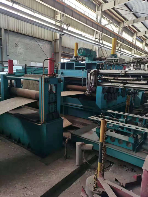
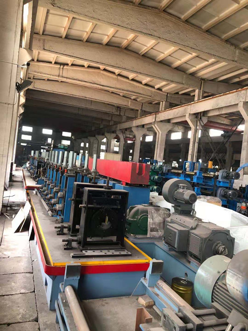
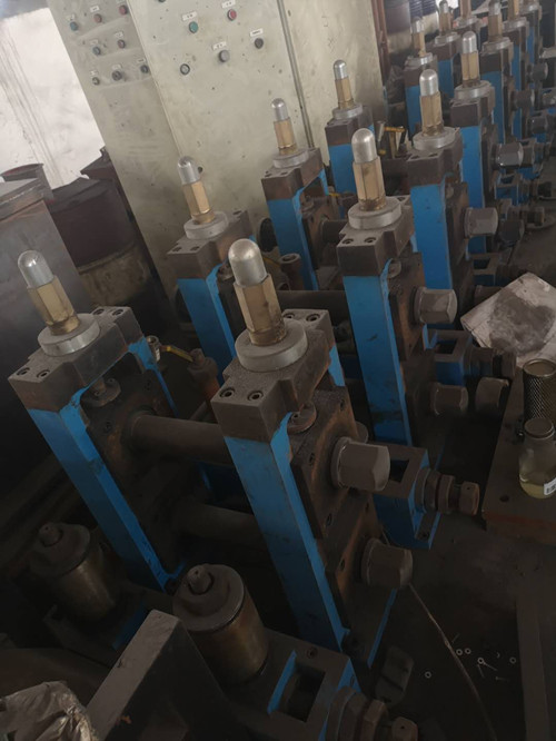
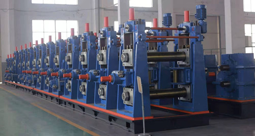
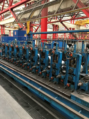
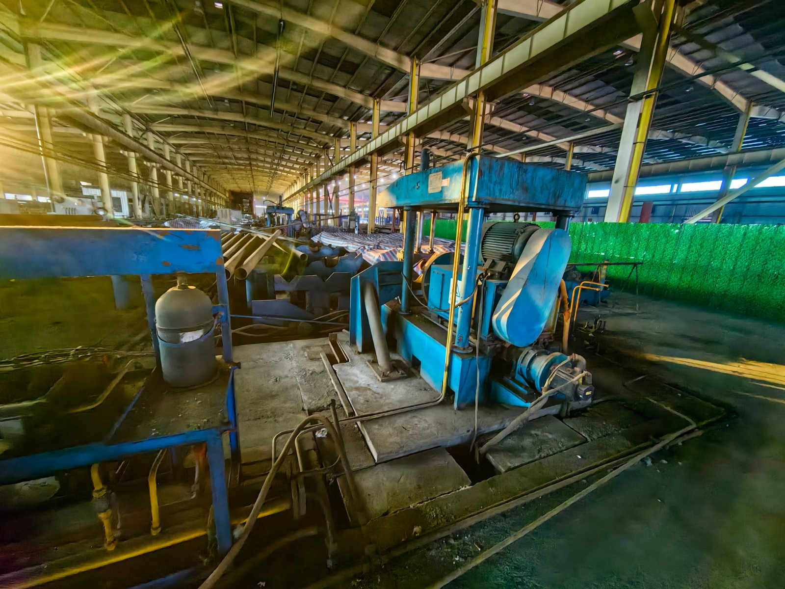
ERW Tube Mill
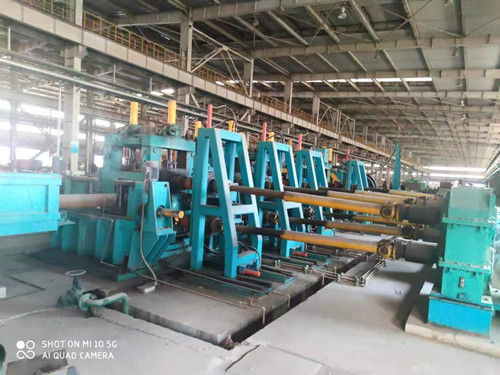
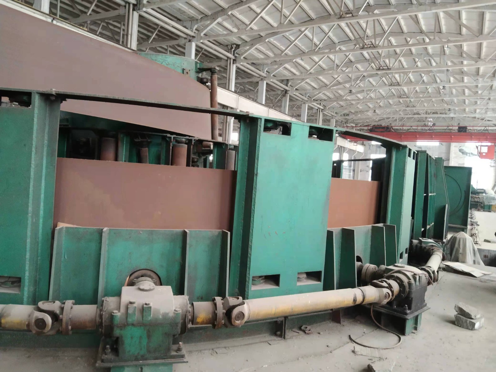
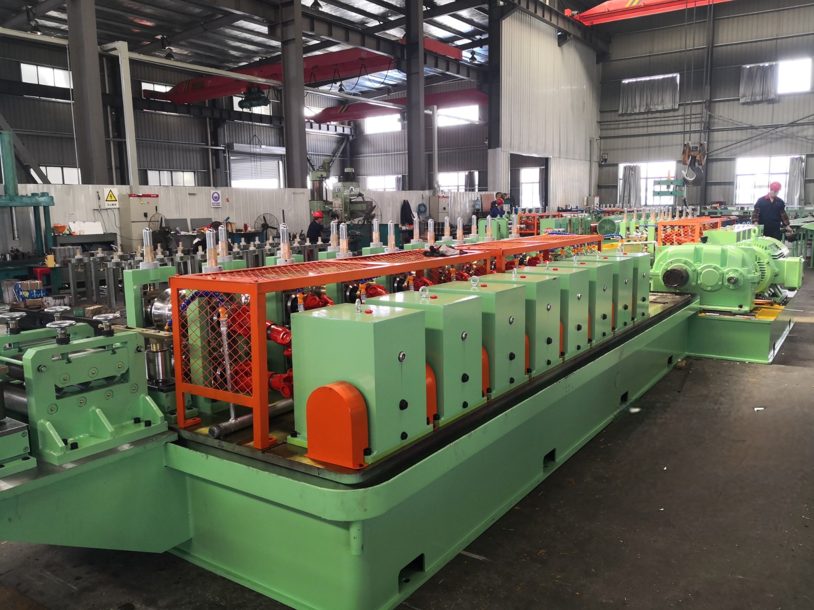
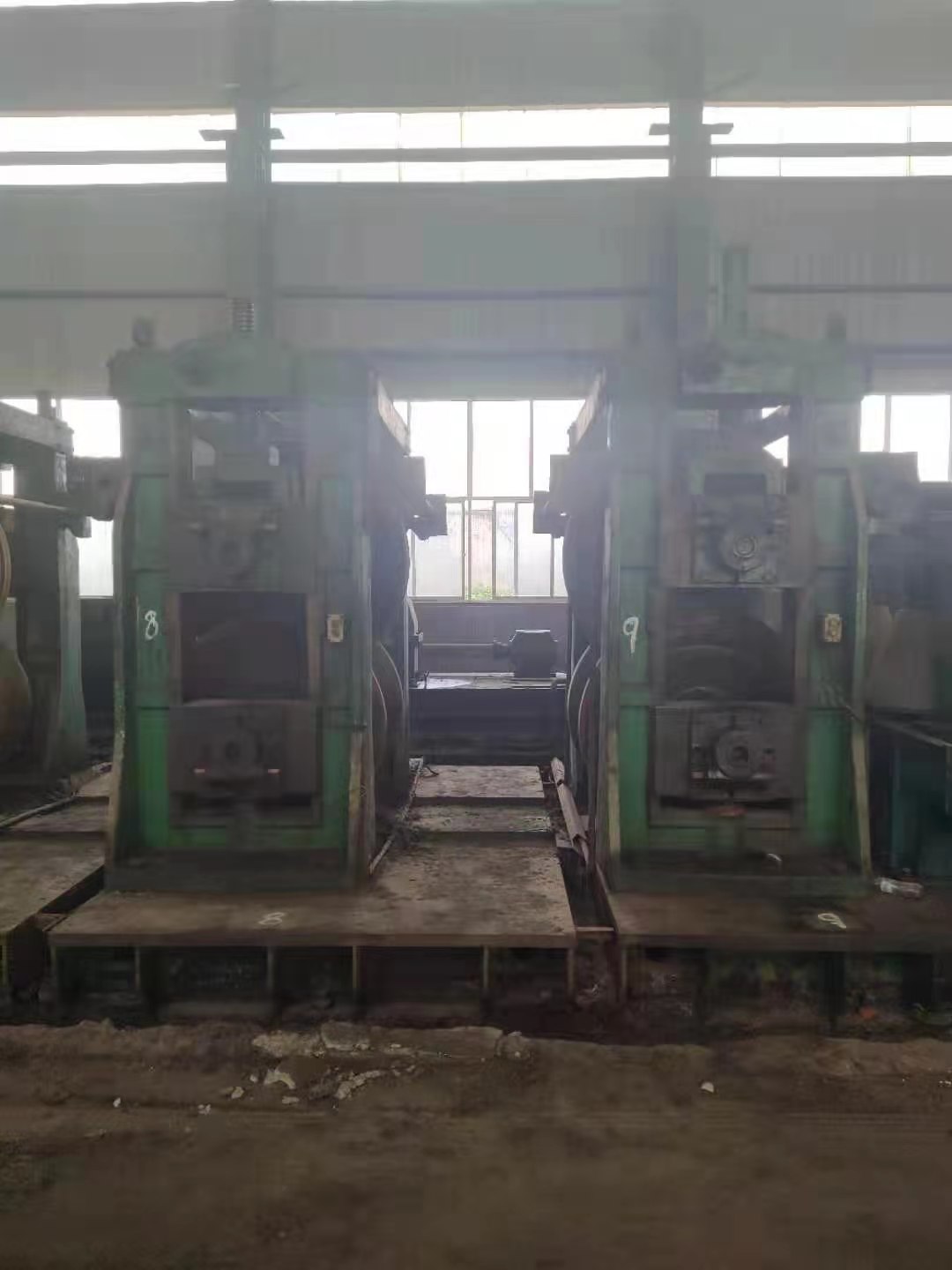
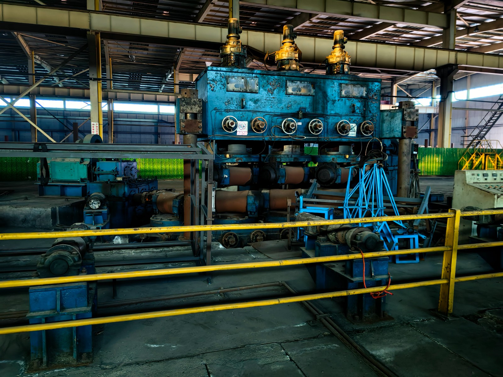
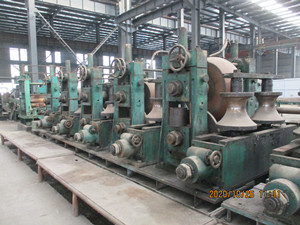
No.189 12 in used ERW API Tubemill
It was made in 2008. The written time is June 29,2021.- product description
- Technical Parameters
Production variety, production capacity and technical data of the production line:
2. 1 unit parameters:
2.1.1 unit speed: 14-40m/min;
2.1.2 forming method: ztf forming;
2.1.3 production direction: left in and out from right (drive end is on wall side)
2.1.4 center elevation: +1000mm;
2.1.5 production capacity: 150000 tons / year
2.1.6 total installed power: about 5000kW (excluding workshop lighting and supporting power)
2.1.7 compressed air:
Flow rate: 10m3 / min
Pressure: 0.7MPa
2.1.7 circulating water source:
Unit water flow: 30 m3 / h
Reservoir volume: 120m3
2.2 product specification range:
2.2.1 diameter of finished steel pipe: φ 114.3- φ 355.6mm
2.2.2 wall thickness of finished steel pipe: 3-14mm (16mm)
(when the material is Q235-B, it is available for production.) Ф 355.6 mmx16mm)
2.2.3 length of finished steel pipe: 6-15mm
2.2.4 precision of ruler: 0-5mm (computer flying saw)
2.3 raw material conditions:
2.3.1 material: suitable for low carbon steel, low alloy structural steel, API Spec 5L X70;
API Spec 5CT ( J55,K55);
Mechanical properties: σ b≤758MPa σ S≤600Mpa
2.3.2 strip width: 350-1105mm
2.3.3 strip thickness: 3-14mm (16mm)
2.3.4 inner diameter of strip coil: 580-760mm
2.3.5 outer diameter of strip coil: 1400-2200mm
2.3.6 coil weight of strip steel: < 35t
Structure selection, configuration and technical performance description of production line equipment
Main equipment parameters:
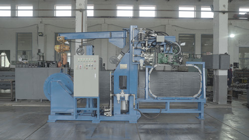
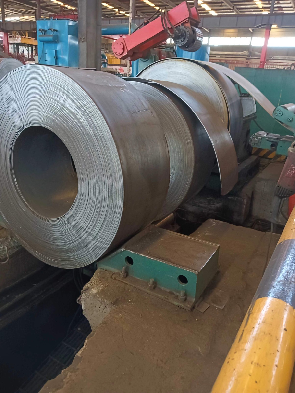
5.1 storage platform
5.1.1 function: storage and release of steel coil
5.1.2 equipment parameters:
Coil outer diameter: φ 1400~ φ 2200mm
Strip width: 350-1105mm
Maximum weight of coil: 35t
Storage capacity of strip steel: 2 rolls
5.1.3 equipment structure:
Two groups of shallow V-shaped plates made of steel are directly fixed on the base of reinforced concrete foundation, and the two groups of shallow V-shaped plates can be adjusted according to the width of steel strip.
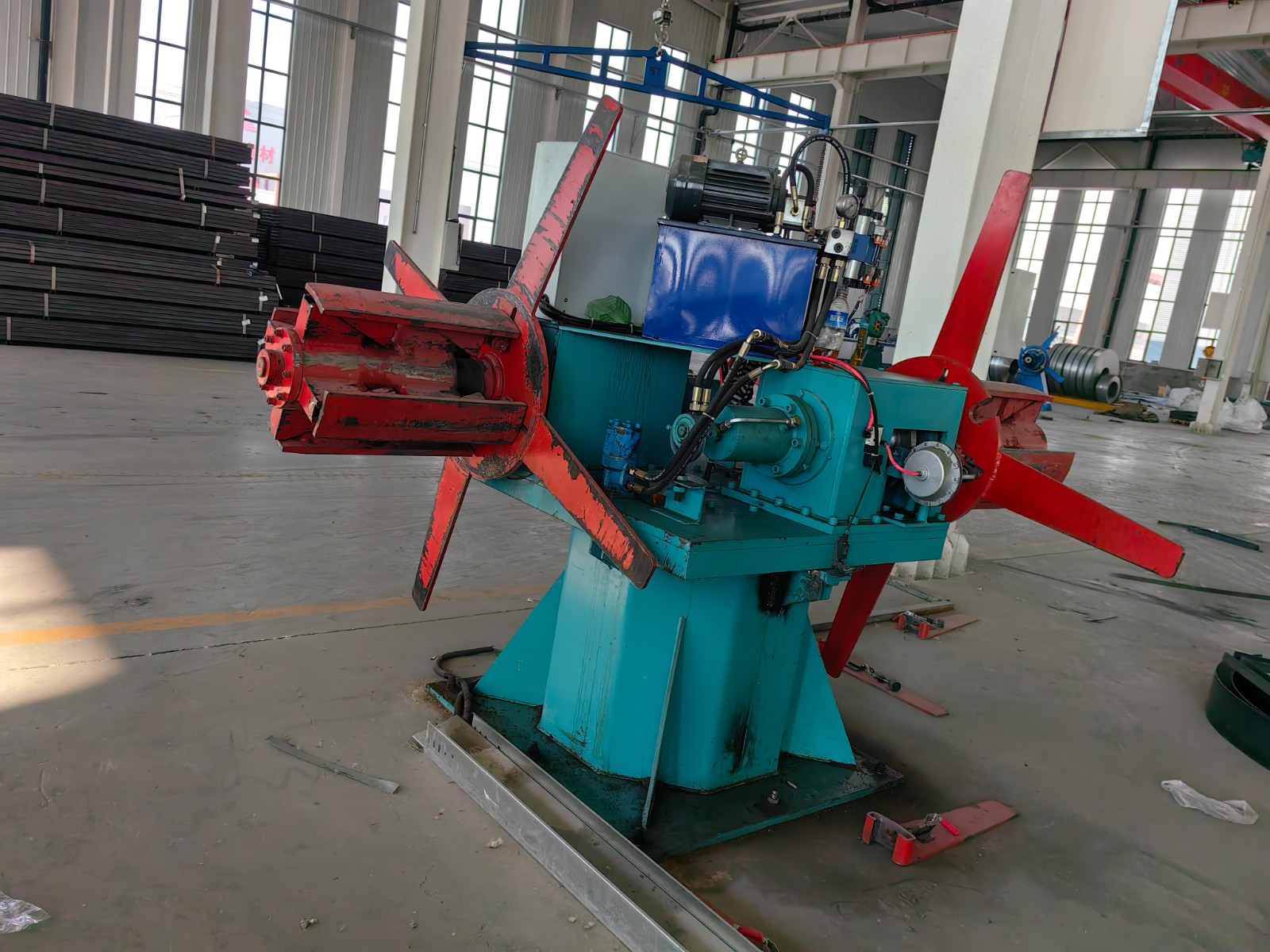
5.2 upper roll car
5.2.1 function: remove the steel coil from the storage platform and send it to the uncoiler.
5.2.2 equipment parameters:
Coil outer diameter: φ 1400~ φ 2200mm
Strip width: 350-1105mm
Maximum weight of coil: 35t
Maximum lifting height of steel coil: 900mm
Lifting cylinder diameter: 220mm
Hydraulic system pressure: 12MPa
Maximum lifting force of lifting cylinder: 40t
Number of guide rods: 4
Trolley travel: hydraulic motor or electric motor
Traveling speed of trolley: 10M / min
Trolley travel: 7M
5.2.3 equipment structure:
The V-shaped lifting platform of the feeding trolley is a four column hydraulic lifting platform, and the trolley is driven by hydraulic motor or electric motor.
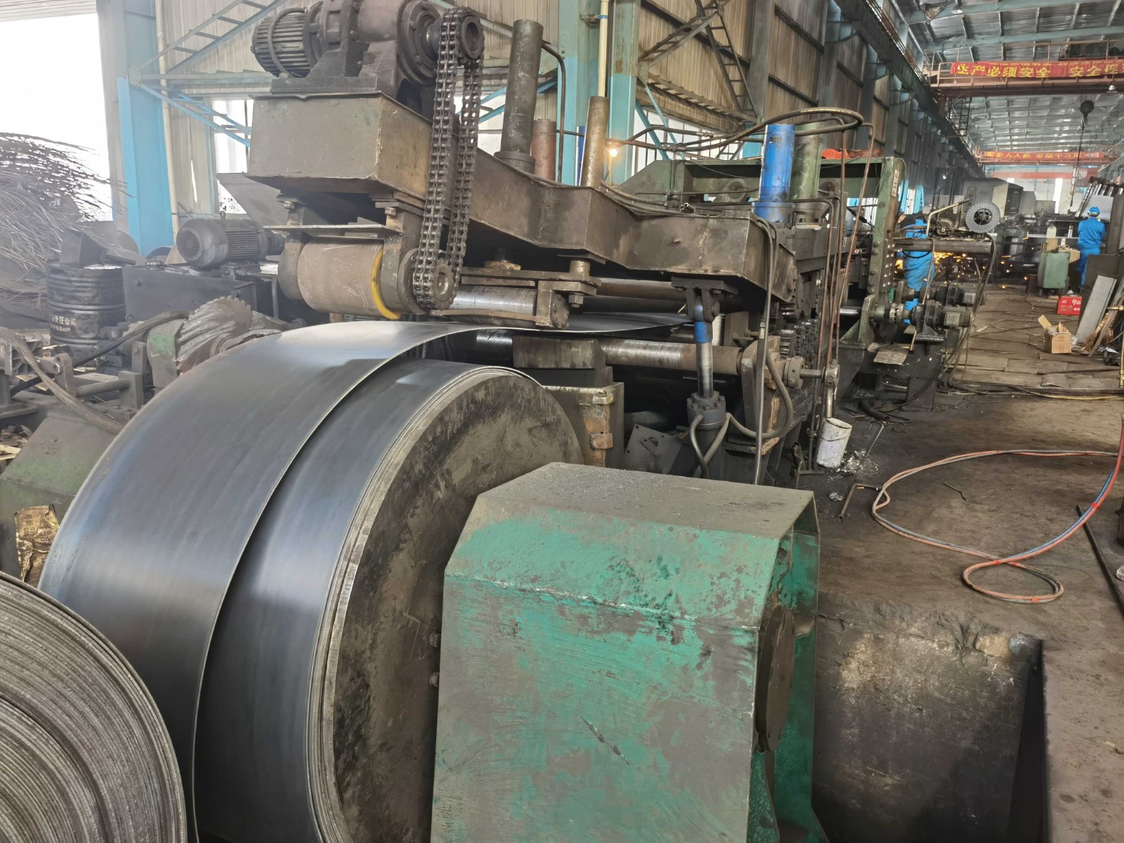
5.3 uncoiler
5.3.1 function: support and expand the steel coil.
5.3.2 equipment parameters:
Coil outer diameter: φ 1400~ φ 2200mm
Strip width: 350-1105mm
Maximum weight of coil: 35t
Base moving distance: 900mm
Cone head outer diameter: φ seven hundred and sixty
Uncoiling mode: upper uncoiling mode
Seeker speed: 12m / min
Drive: cone drive hydraulic motor or motor
5.3.3 equipment structure:
It adopts double cone head expansion mechanism, hydraulic motor and brake drive cone head uncoiling, and has micro tension performance. The double cone head adopts hydraulic centering.
5.4 coil opener
5.4.1 function: press the steel coil head and shovel it off.
5.4.2 equipment parameters:
Coil outer diameter: φ 1400~ φ 2200mm
Strip width: 350-1105mm
Outer diameter of pressure roller: 300 mm
Pressure roller drive motor: ac5.5kw
Uncoiling speed: 15m / min
5.4.3 equipment structure:
The upper pressure roller is a steel roller with rubber structure, which is controlled by hydraulic cylinder and driven by motor. It drives the coil to rotate when uncoiling. The blade controlled by hydraulic cylinder can stretch and swing according to the diameter of the steel coil to be dismantled, which can adapt to the dismantling head of the steel coil with various size requirements.
5.5 feed leveler
5.5.1 function: introduce the strip head from the uncoiler to level the strip. In addition, it can run synchronously with the looper feeder for active leveling, and can also open the transmission clutch for passive leveling.
5.5.2 technical parameters:
Strip width: 350-1105mm
Strip thickness: 3-14mm (16mm)
Drive motor: ac45kw
Feeding speed: 8 ~ 30m / min
Hydraulic system pressure: 10MPa
Flattening roller Screwdown Motor: ac3kw × two
Diameter of feeding roller: φ three hundred and eighty × 2140 material: 42CrMo
Diameter of leveling roll: φ two hundred × 2140 material: 42CrMo
Press down cylinder of feeding roller: φ two hundred × four hundred
5.5.3 mechanism: the upper and lower feeding roller is pressed down by hydraulic pressure. Five leveling rolls (upper 2 / lower 3), including mechanical reduction system, balance system, universal drive shaft, reducer, clutch, motor, etc( Up and down active, upper roll can be monotonous)
The leveling roller is pressed down by motor, reducer, worm gear pair and screw rod. High performance balancing system for upper roll screwdown (adjustment needs digital display).
5.6 shear butt welding machine
5.6.1 function: the leveled strip head enters the machine and connects with the tail of the previous roll. In order to realize continuous production of welded pipe, the head and tail shall be cut, and the gap shall be adjusted before welding, namely, the shearing butt welding process shall be completed.
5.6.2 equipment parameters:
Strip width: 350-1105mm
Strip thickness: 3-14mm (16mm)
Strip grade: up to X70 API 5L; J55 K55 API 5CT
Material properties: σ b≤758MPa σ S≤600Mpa
Hydraulic system pressure: 16MPa
Cutting mode: Hydraulic up cutting (up cutting and down cutting)
Bevel angle: 5 ° Irregularity of steel plate after welding ± 6mm, dislocation: ≤ 1.5mm
Weld bead height after welding: ≤ 1 mm
Butt welding time parameter table: plate thickness ≤ 10mm max.8min
Plate thickness > 10 mm max.9 min
5.6.3 equipment structure: it consists of bed, centering device, shearing machine, forward plate moving machine, back plate shifting machine, driving system, welding device and hydraulic system. The pinch device is composed of inlet guide roll and outlet guide roll. The hydraulic shear is composed of upper crossbeam, upper shear blade and lower shear blade, guide post, oil cylinder, shear plate, etc. Up cutting type oblique cutting edge.
The bed can move laterally through the guide rail, so that it can ensure the accurate position of each function, that is, the head and tail should leave the weld according to the process requirements, and the welding gun should find the weld accurately and weld automatically( Including welding system)
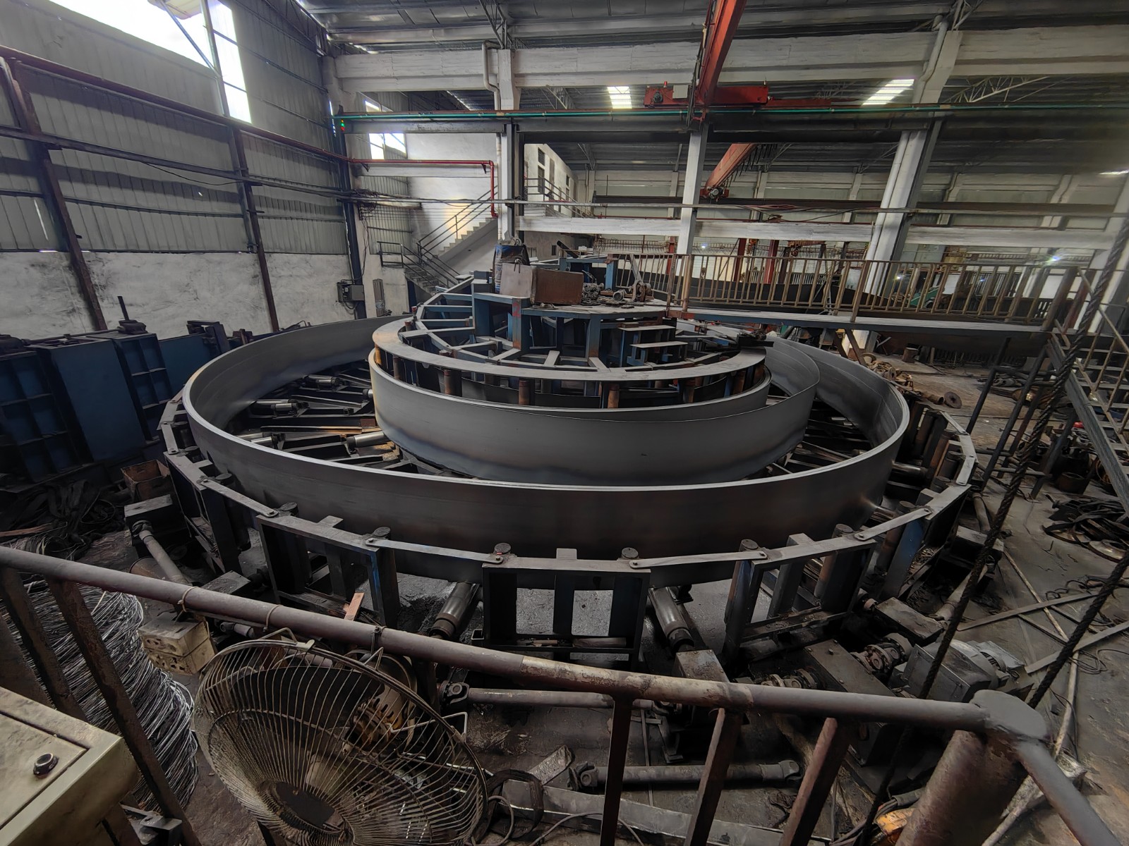
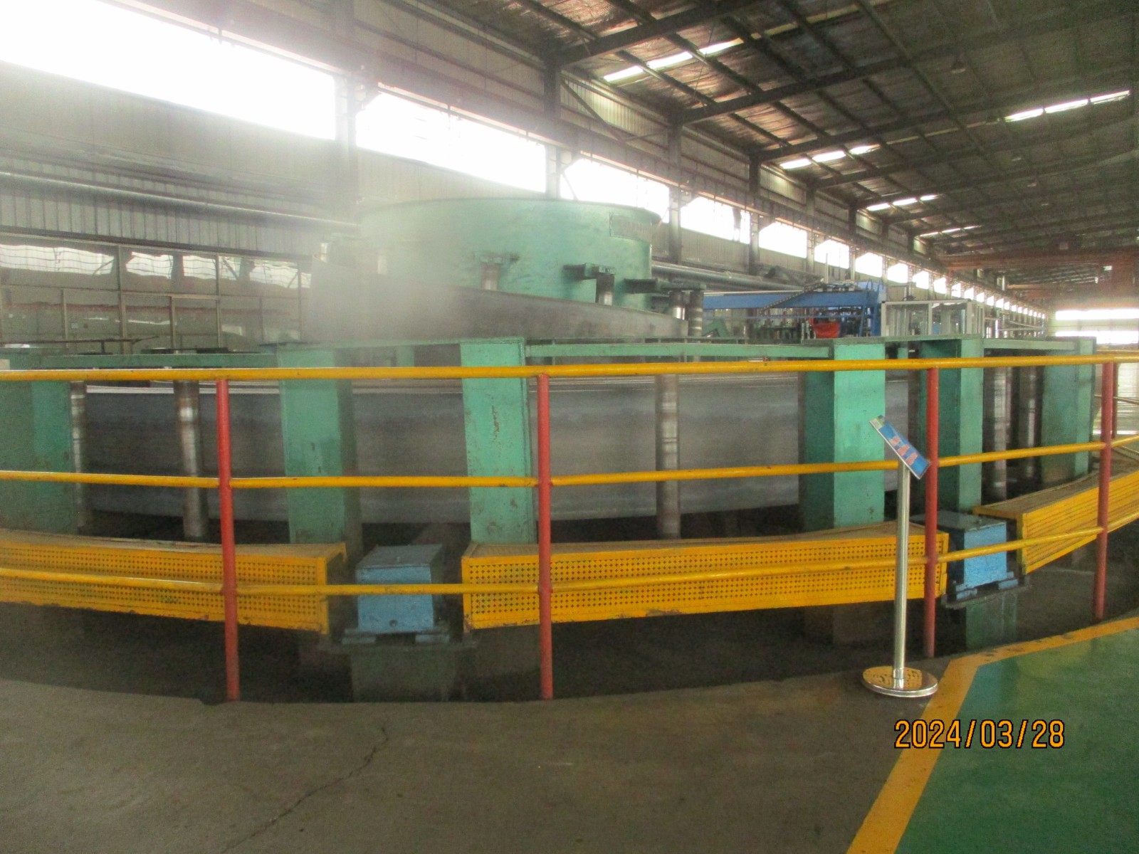
5.7 horizontal accumulator
5.7.1 function: horizontal spiral looper is used to store the steel strip to store the butt connected strip into the looper, and supply the material for the forming sizing unit. Under the condition of continuous production of the forming sizing unit, the time interval is provided for the completion of the connection work of the coil. The looper is a fixed ring system, which works in and out from the outside. During the working process, the number of steel belt turns in the looper remains unchanged. The looper is easy to install and operate, and the steel belt does not fold repeatedly in the looper, and there is no local plastic deformation. The discharge is smooth, the discharge resistance is small, and the steel belt has no plastic deformation. The energy consumption, roller consumption and bearing wear of the forming and sizing unit are low, The weld quality and yield can be improved.
Strip thickness 3~14mm(16mm)
strip width 350~1105mm
Storage length 400-600m (inner diameter 8000mm)
Charging speed Max 120m/min
Charging motor power Ac110kw (forward and reverse) digital speed regulating unit
Bottom roller motor power Ac5.5kwx24 (forward and reverse) digital speed regulating units
Hydraulic system pressure 10MPa
5.7.2 equipment parameters:
Thickness of steel plate: 3-14mm (16mm)
Width of steel plate: 350-1105mm
Charging speed: max20m / min
5.7.3 equipment structure: it consists of the front torsion device, feeding machine, rear torsion device and transmission device of strip steel. The machine has its own protection function, and can operate normally when the thickness of the plate changes suddenly.
5.8 ultrasonic detection of steel strip (not within the scope of supply)
5.9 edge milling machine (not within the scope of supply)
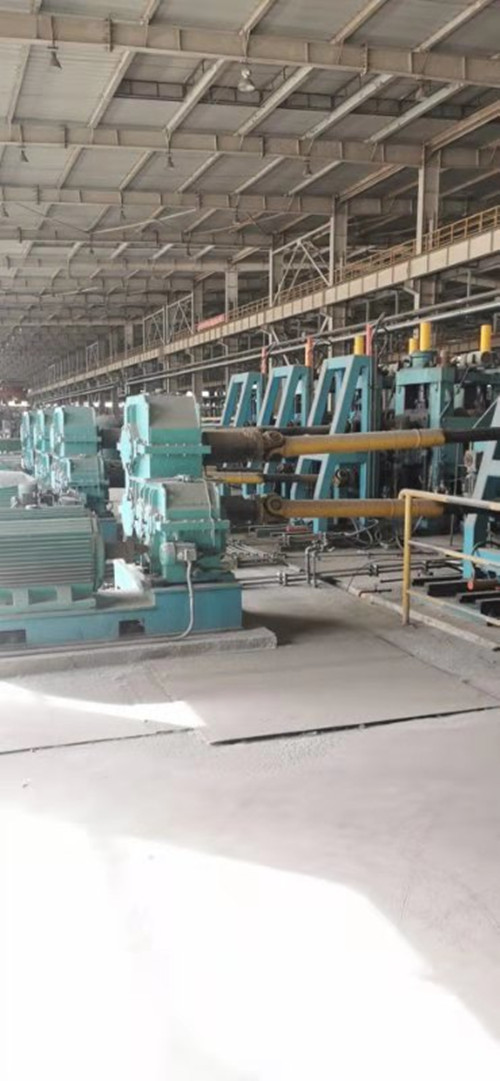
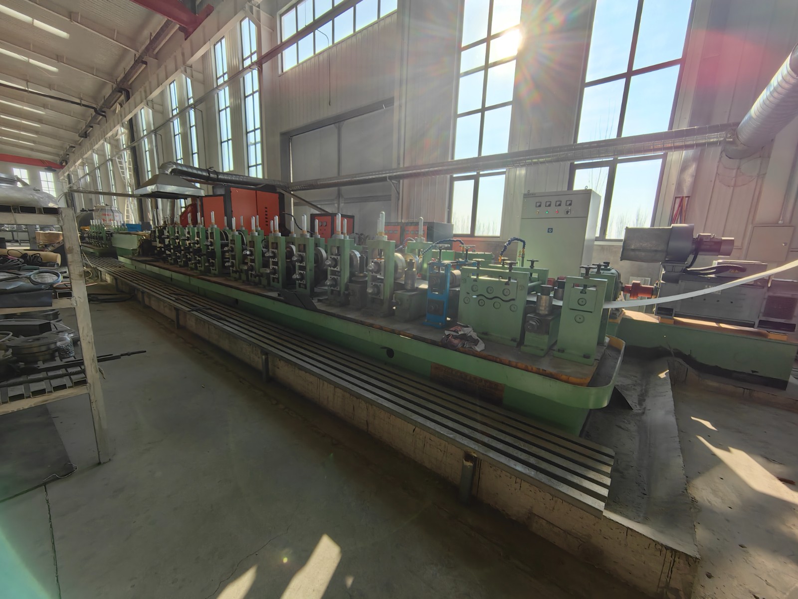
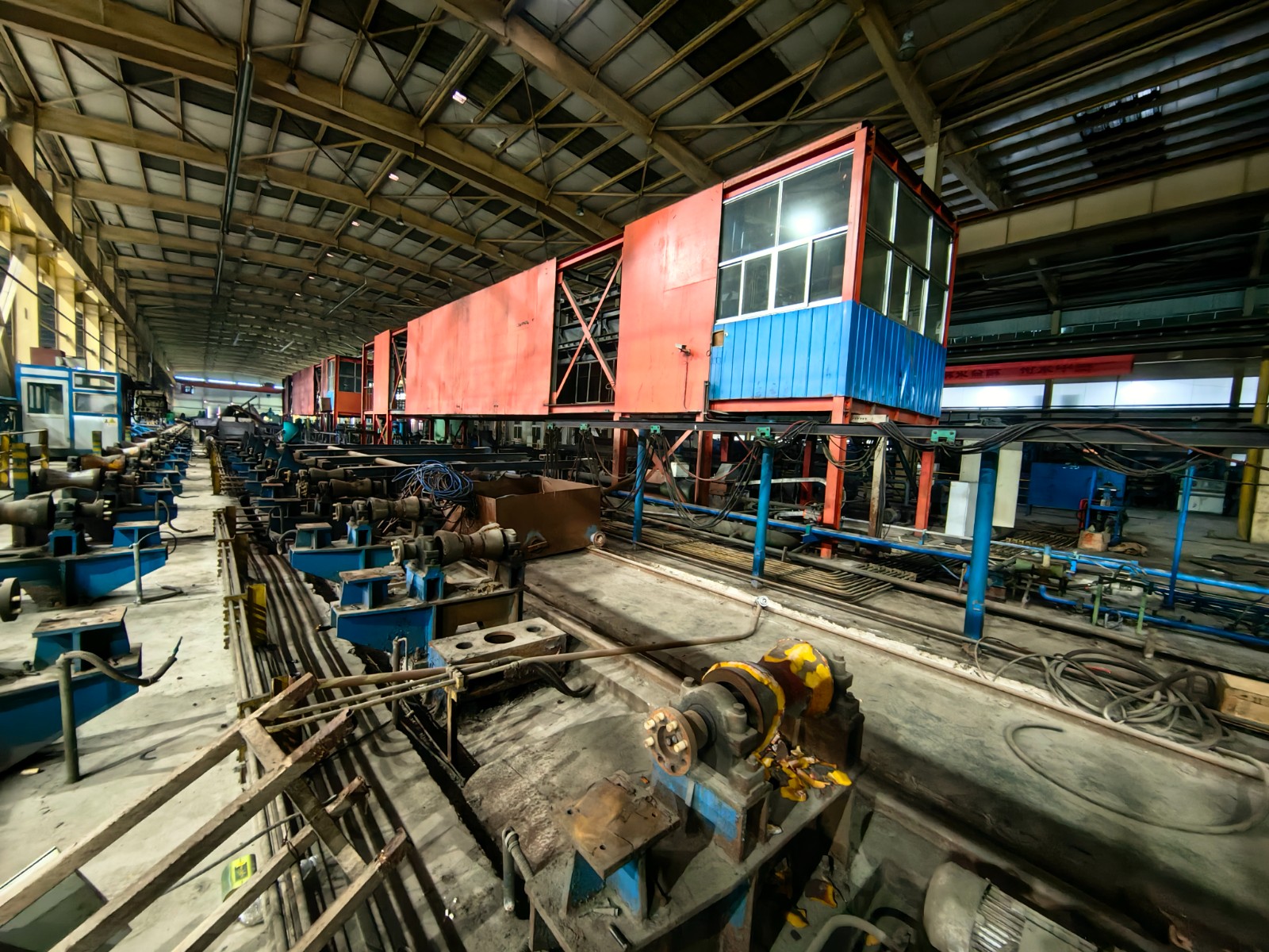
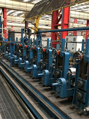
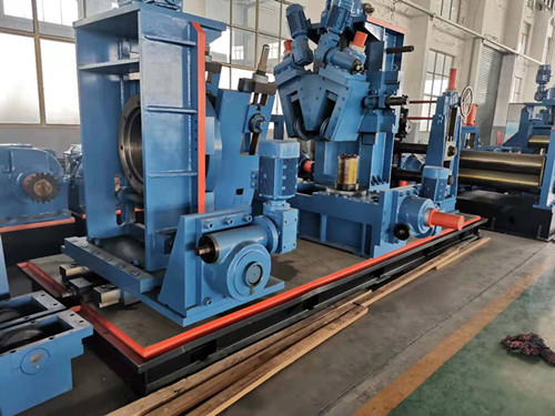
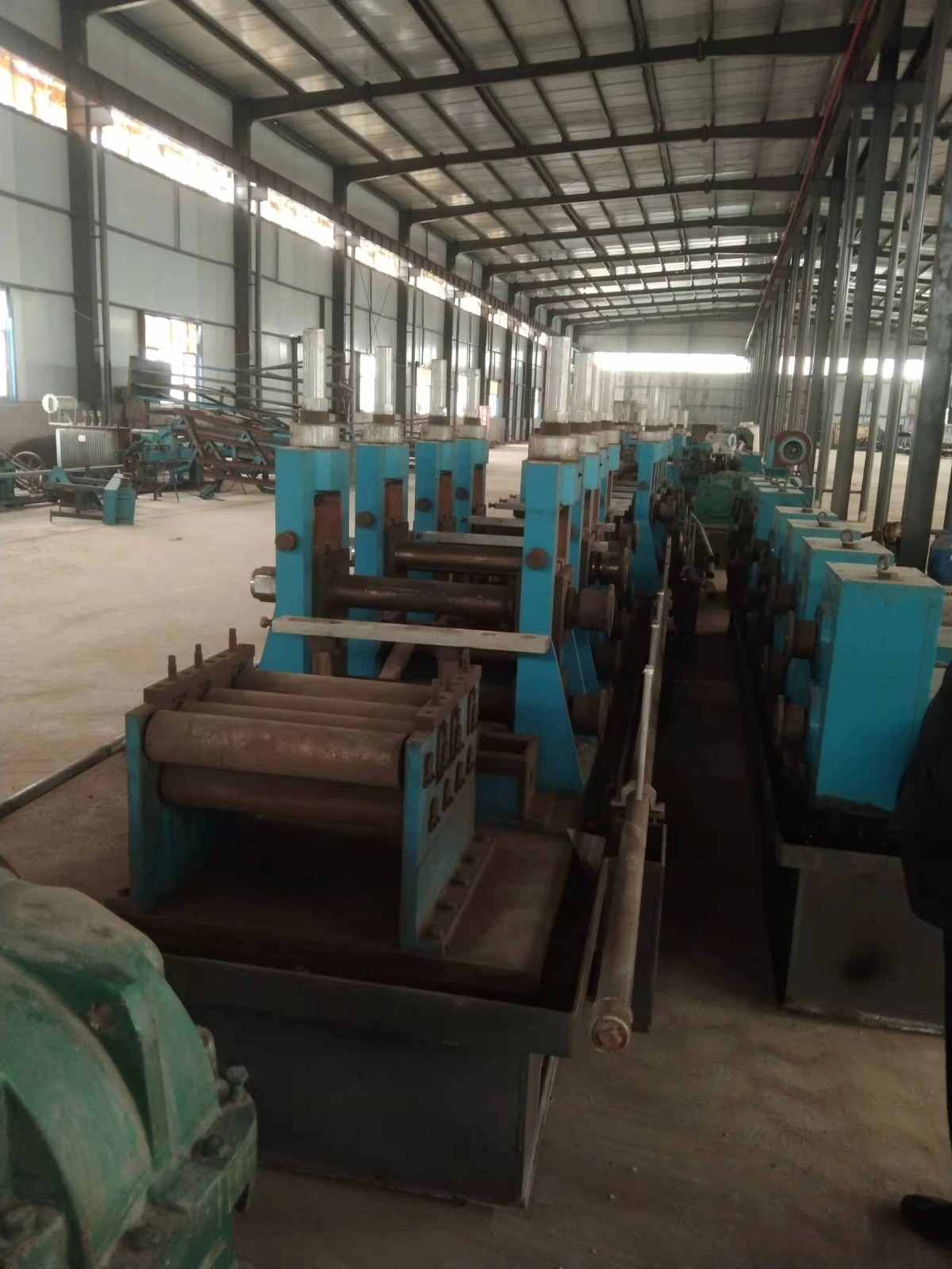
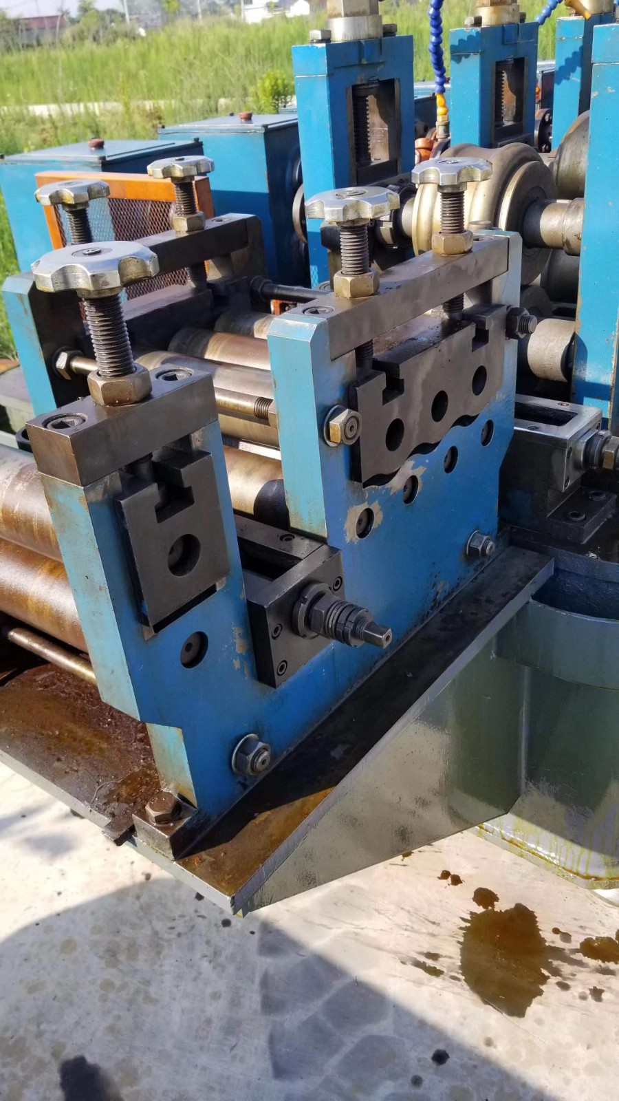
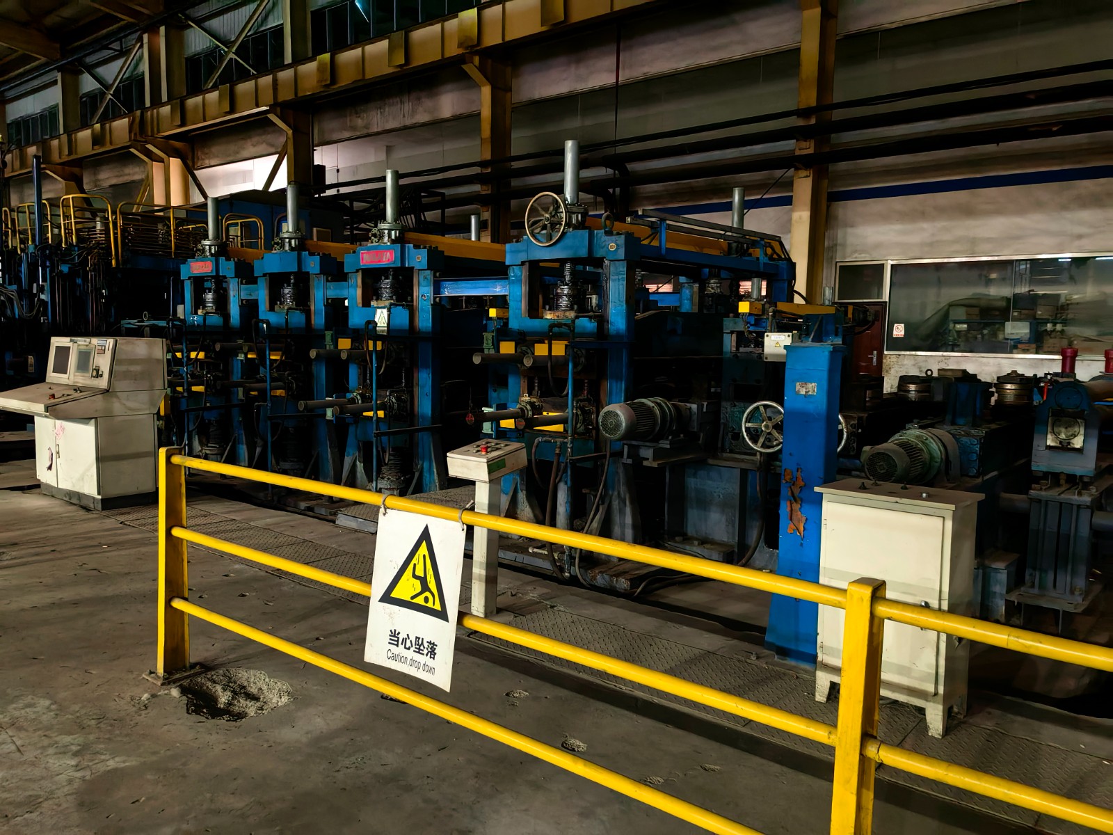
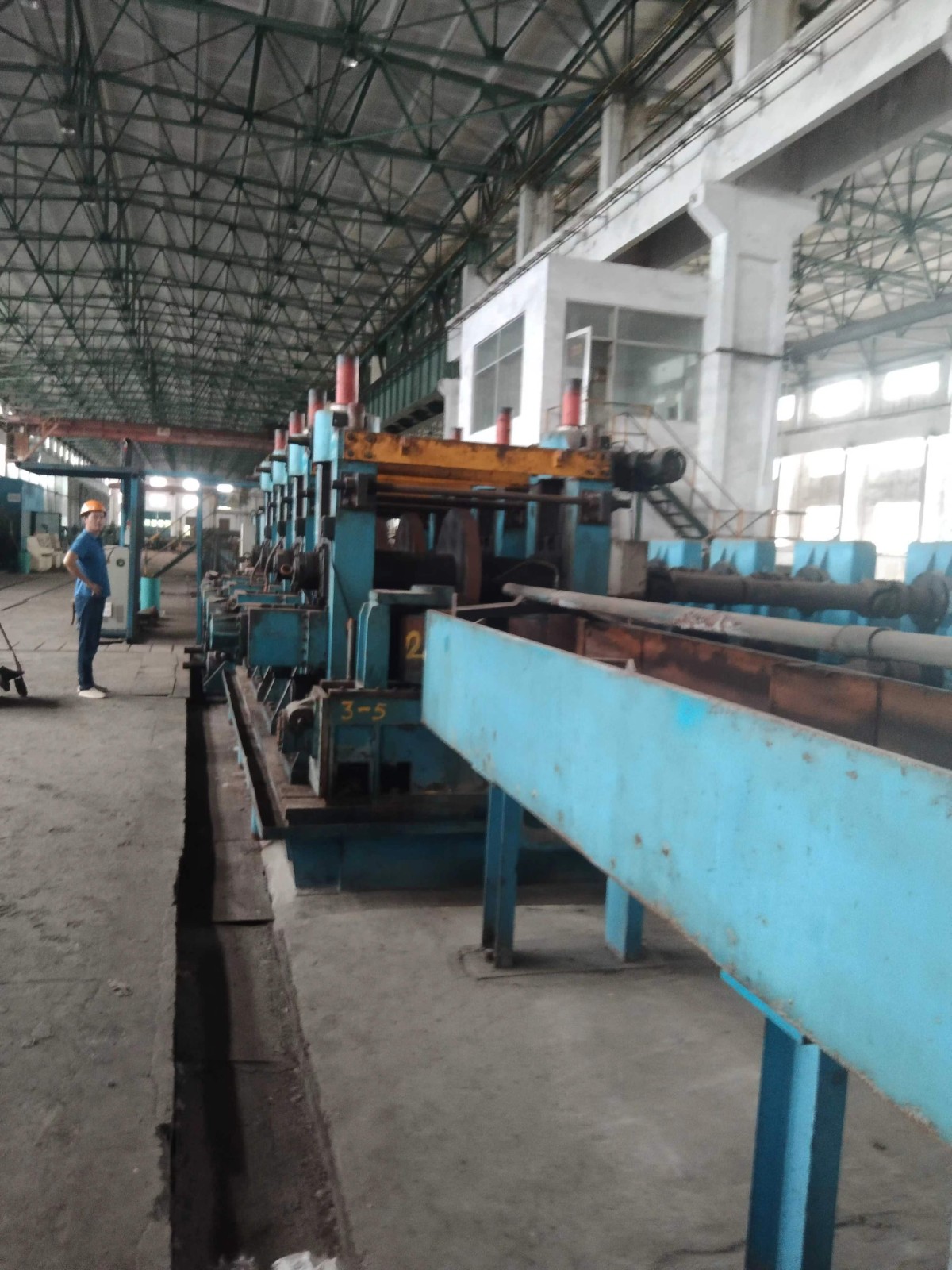
5.10 forming and sizing unit
Forming 10 flat rolls, 6 rotary vertical rolls; One frame polished; 4 flat rolls for sizing; 3 vertical rollers;
2 sets of rough straightening
There are 15 motors, all of which are AC variable frequency adjustable speed motors
75kW 8 sets, 110KW 7 sets
There are 15 reducers, all of which are hard gear reducers
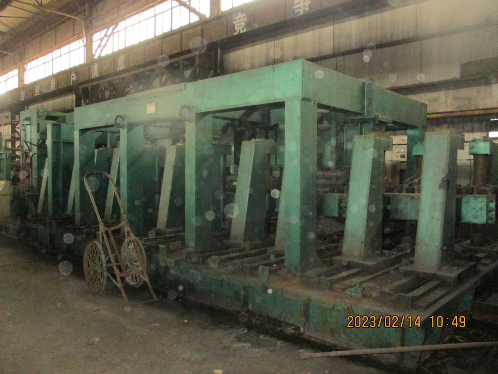
5.10.1 forming unit
5.10.1.1 rough forming section:
Number of forming frames: 7
Rack spacing: 1800mm;
Frame structure: gantry type
Adjustment mode and range of rough forming roll:
(1) Strip feeding device:
It can be used to ensure that the strip steel is accurately guided into the first forming frame. It consists of a pair of horizontal rolls and two vertical rolls. The opening and closing of the two vertical rollers are adjusted by the motor drive, and the rollers need not be replaced, so they are completely shared.
(2) The first horizontal frame:
Pinch roll, the sheet into the next frame, at the same time participate in part of the deformation. The height of the lower roll is fixed, the height of the upper roll is adjusted by the worm gear box driven by the motor, and the prestressed disc spring assembly is used as a safety device against overload. The motor is controlled by the computer and adjusted automatically. The roller is not needed to be replaced and is completely shared. The roller shaft is driven by a motor through a reducer and a universal joint shaft. The upper and lower shafts are active transmission.
(3) , the second and third horizontal frames:
It is used for bending edge forming. The lower roller is installed on two sliding seats. Two motors drive the two sliding seats to slide on the lower shaft for opening and closing adjustment. The sliding seat and the lower roller shaft are installed in the lifting chute. The chute is driven by one motor for lifting adjustment in the frame. In this way, when the lower roll is under forming force, the force is transferred from the sliding seat to the chute and borne by the frame, so the roll shaft will not be subject to great force.
Two rotatable upper rollers are also installed in a chute, and the chute is driven by two motors at the same time for lifting adjustment in the frame. The rotation of the two rollers is also driven and adjusted by two motors respectively, and the opening and closing of the two rollers are also driven and adjusted by two motors respectively.
All adjusting motors are controlled by computer, automatic adjustment, roll does not need to be replaced, completely shared. The lower roller shaft is driven by a motor through a reducer and a universal joint shaft. The upper axis is passive.
(4) The fourth, fifth and sixth horizontal frames:
It is used to bend the edge and part of the waist. The upper roller is installed on two sliding seats, and the two sliding seats are driven by two motors to slide on the upper shaft for opening and closing adjustment. The sliding seat and the upper roller shaft are installed in the lifting chute, and the two motors drive the chute in the frame for lifting adjustment. In this way, when the upper roll is under forming force, the force is transferred from the sliding seat to the chute and borne by the frame, so the roll shaft will not be subject to great force.
The lower roll is fixed on the lower roll shaft without adjustment and replacement.
The side roll frame together with the lower roll shaft is installed in the sliding groove, and the sliding groove is driven by a motor for lifting adjustment in the frame. The side roller frame is fixed on the chute and can slide on the chute. The two side roller frames are respectively driven by two motors for opening and closing adjustment. The height of each side vertical roller is fixed. In order to meet the product specifications, the sixth side vertical roller is made into a tower roller.
All adjusting motors are controlled by computer, automatic adjustment, roll does not need to be replaced, completely shared. The upper and lower roller shafts are driven by motor through reducer and universal joint shaft. They were all active.
(5) The seventh horizontal frame:
It is used to bend the waist and provide power for the rotating vertical roller group. The height of the lower roll is raised and lowered by a motor driven elevator, and the height of the upper roll is raised and lowered by a motor driven worm gear box. The prestressed disc spring assembly is used as a safety device against overload. The side roll frame is installed on the frame and is driven by the motor for opening and closing adjustment. The height of the side roll can be adjusted by the worm gear box to meet the needs of high precision tube fine adjustment.
All adjusting motors are controlled by computer, automatic adjustment, roll does not need to be replaced, completely shared. The upper and lower roller shafts are driven by motor through reducer and universal joint shaft. They were all active.
(6) Rotary vertical roller group:
For the waist molding, a total of six, arranged in two groups.
The opening and closing of the two rollers are adjusted by a motor, the lifting and lowering of the two rollers are adjusted by a motor, and the rotation of the two rollers is adjusted by two motors,
All adjusting motors are controlled by computer, automatic adjustment, roll does not need to be replaced, completely shared.
(7) All frames are cooled and lubricated by emulsion supplied to the forming roller through the nozzle. All shafts are supported by rolling bearings. This design can ensure smooth operation, high efficiency, low noise and long service life. The main drive of the forming machine adopts AC variable frequency speed regulating motor, which is separately driven by the reducer. The electric control system controls the synchronization of each frame, and realizes stepless speed regulation, so as to meet the needs of product forming speed.
5.10.1.2 roll change mode of roughing machine:
The rolls in the rough forming section are completely shared, and there is no need to replace or disassemble them. They are only controlled by the computer and adjusted by the motor.
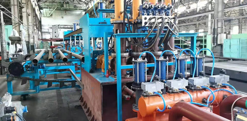
5.10.1.3 structure of vertical roller group:
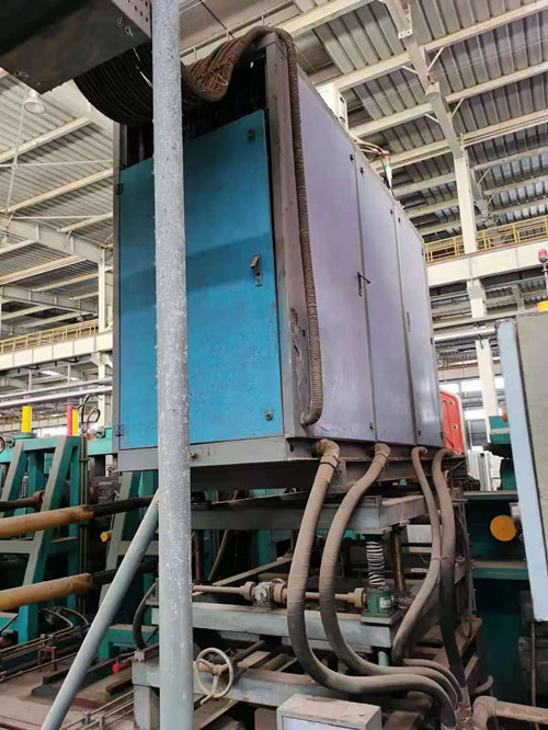
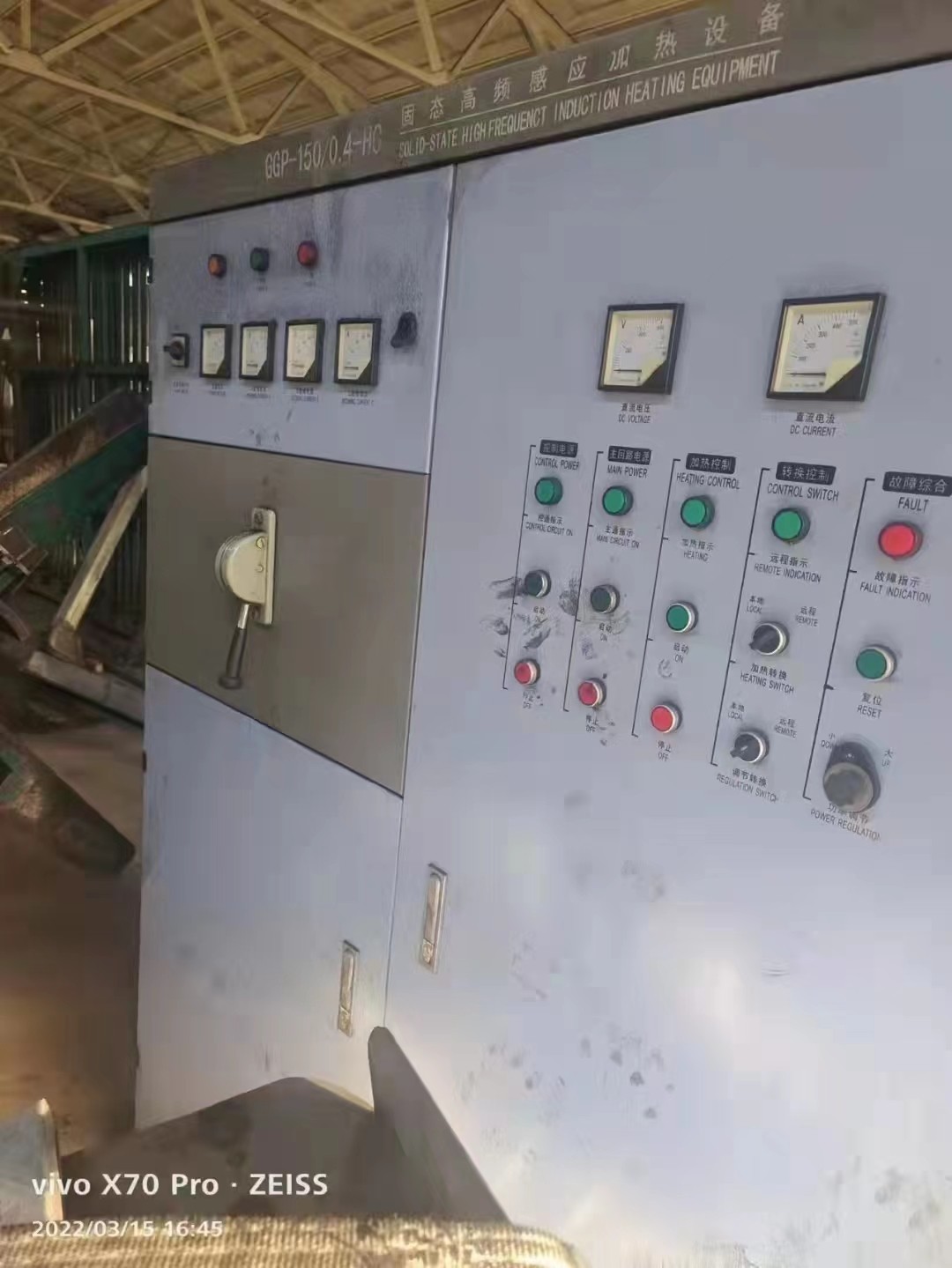
Function: extrude and weld the tube side heated by high frequency.
Equipment parameters:
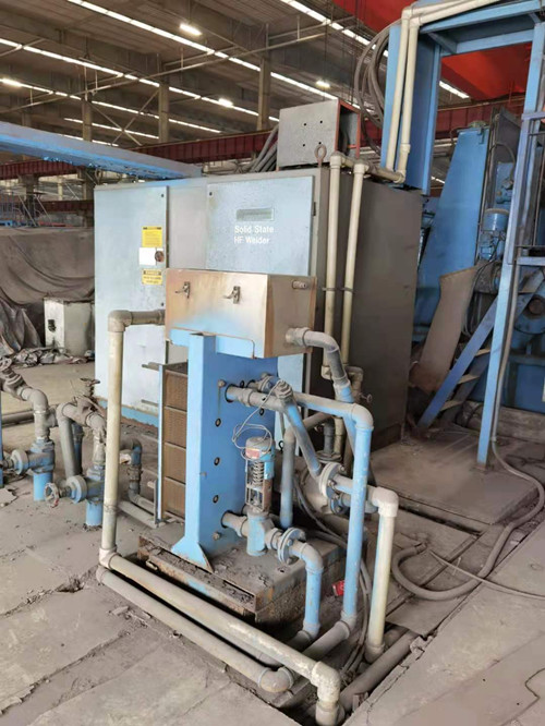
Solid state induction contact dual purpose high frequency welding machine 800-1200kw
Main extrusion roller shaft diameter: 250mm, material: 42CrMo;
Shaft diameter of upper roll: φ 130mm, material: 40Cr; The upper roll can be adjusted horizontally.
Equipment structure: five roll extrusion welding device, five roll extrusion welding combination is left and right inclined down roll, left and right vertical roll, in addition, there is a group of top roll. The upper and lower rolls are divided into two groups, which are respectively installed in two semi arc brackets. By adjusting the arc bracket longitudinally, the radial expansion of the extrusion roll can be realized, so as to achieve the purpose of adjusting the extrusion pressure, It can also be adjusted manually to achieve the guiding effect. When changing the roll, replace the pre installed roll base and frame type welding frame.
5.10.4 external burr removal function:
Planed the outer weld and automatically cleaned the waste wire into the material basket outside the equipment
Equipment parameters:
Adjustment range height direction: 260mm
Horizontal direction: 50mm
Number of planers: 2
Tool specification: 40 × 40mm
Roughness after planing: RA ≤ 25um
Number of planers: 2 (one for use and one for standby)
Cutter head material: cemented carbide
Equipment structure: deburring device. There are two sets of mechanical planers, one for standby, with elevator adjustment up and down, and pneumatic quick lifting mechanism for quick adjustment. The main thorn is collected after chip breaking.
5.10.5 weld flattening frame: 1 frame
As the frame in front of the cooling device, it is used to stabilize the movement state of the steel pipe and press the uneven part of the planer before the steel pipe is completely cooled.
Equipment parameters:
Horizontal shaft diameter: 240mm
Upper roll adjustment: 260mm
The roll does not need to be replaced;
Motor power; 75kW, AC motor frequency control
Equipment structure: the frame consists of frame, upper and lower horizontal roller bases, and the upper and lower rollers are moving; Electric adjustment of upper roller, digital display; It has quick change function.
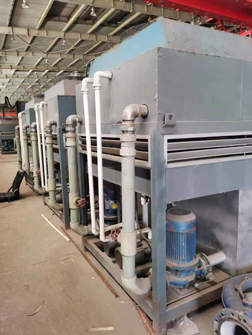
5.10.6 weld water cooling device: 1 set
Function: the steel pipe is air-cooled and water-cooled after high-frequency heating welding and medium frequency heating annealing, so that the surface temperature of the steel pipe weld does not exceed 300 ℃ ° C. In order to enter the shaping section for further shaping and straightening.
Equipment parameters: cooling capacity
Coolant flow: 25m3 / h
The working pressure of coolant is 0.3MPa
Effective cooling length of air cooling: 65000mm
Effective cooling length of water cooling: 8000mm
Surface temperature of outlet weld of cooling equipment: no more than 50 ℃ ° C
Equipment structure: weld cooling device is composed of air cooling section, circulating water tank, circulating water system and steel pipe guide device. The welding seam is cooled effectively to avoid the bending deformation of the product due to uneven or insufficient cooling. The upper, lower, left and right guide devices are equipped in the cooling section to ensure that the steel pipe head enters the shaping frame. The guide device has enough rigidity and easy disassembly.
5.10.7 sizing unit
Number of sizing frames: 4
Number of inserted vertical rollers: 4
The number of vertical roller with straight axis; 1
The parameters, adjustment mode and roll changing mode of sizing unit are the same as those of fine forming
5.10.8 Turkey head straightening frame (single side)
Function: correct the bending and torsion of the product. Number of Turkish heads: 2 sets
Equipment parameters:
Distance between straightening frame and last shaping frame: 2400mm
Roll material: 42CrMo
Roller radial adjusting motor: ac1.5kw × two
Horizontal adjustment motor: ac4kw
Vertical adjustment motor: ac4kw
Roll radial adjustment: 130mm
Roll axial adjustment: 130mm
Equipment structure: Turkey head straightener is set up after the last sizing frame, which is composed of two frames arranged together to form the correction and straightening of steel pipe with sizing frame( Turkey frame is installed in the front and back of the fourth sizing frame (1 each)
Solid state welder: 1000kw one set
seam MF induction annealing machine, 600kw, 3 sets
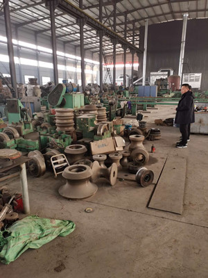
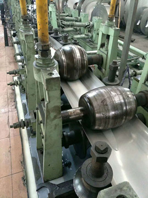
5.11. Roll
Roll material: 9Cr2Mo
Hardness of roll: HRC58-62
Depth of hardened layer: ≥ 10mm
Surface roughness: RA ≤ 0.8um
Description of roll configuration process;
The advanced "ztf" roll forming system is used in the production of round pipe. The roll in the open forming section can meet the forming requirements of various specifications of steel pipe, φ 114- φ There is no need to change rolls in the open forming area, and the commonality of rolls is more than 60%. In the process of roll matching, the specification can be changed only by adjusting the distance and angle of rolls.
Roll sizes: OD 114mm, 139.7mm, 168.3, 177.8, 244.5, 273, 132, 339.7, 355.6mm , 9 sets
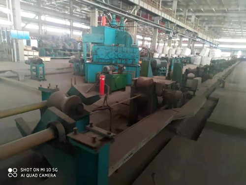
5.12 milling cutter
Function: the fixed length cutting machine adopts two pieces of circular cutters for radial milling and cutting, and is controlled by computer program to meet the requirements of fixed length cutting.
Technical parameters:
Specification of steel pipe: φ 114.3- φ 355.6mm
Steel pipe wall thickness: 3-14mm (16mm)
Length: 6-15m
Length accuracy: 0-6mm
Milling blade: 2 pieces
Milling motor: ac55kw
Traction motor: ac-s47kw
Hydraulic system pressure: 10MPa
-The steel pipe is cut by radial milling with two circular cutters.
-It adopts numerical control operation mode.
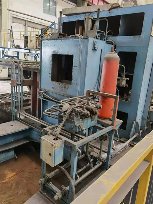
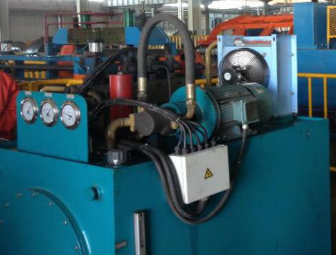
5.13 hydraulic system
Provide low pressure or high pressure oil for all hydraulic cylinders in the production line.
The hydraulic system consists of pump station, valve station, cooling system and pipeline. Rexroth series valves are selected.
Ambient temperature: 10-45 ° C
Oil pressure medium: l-hm46 anti-wear hydraulic oil (if the ambient temperature is too low or too high, use the oil recommended by the oil company)
5.14 pneumatic system
Function: provide pneumatic control for each part to meet the action requirements.
All indexes of compressed air:
Purity: 0.5g/nm3
Particle size: 10-15 max μ m
Oil content: < 5g / Nm3
Dew point: - 40 ℃ (under standard atmospheric pressure)
Temperature: ambient temperature
Pressure: 0.5-0.8mpa
Consumption: 300nm3 / h
Maximum flow: 700 Nm3 / h
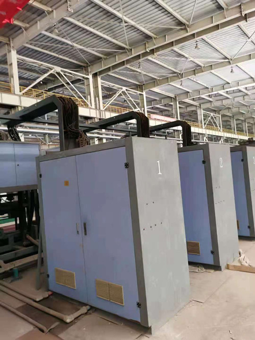
5.15 electric control system
1. Main motor
1.1 control object:
Rough forming main motor 75KW × 7 (AC variable frequency motor)
Precision forming and sizing 110kw × 7 (AC variable frequency motor)
Pull out the main motor 75kW × 1 (AC variable frequency motor)
1.2 control system scheme:
15 main motors are controlled by Yaskawa inverter (four quadrant reversible, encoder position feedback)
YASKAWA inverter data: speed feedback
② Current
③ Speed setting
It communicates with high performance PLC through PROFIBUS, and high performance PLC communicates with 12 inch LCD touch screen. The LCD touch screen is used to control and adjust the rotation of each motor. The interface can set the speed reduction ratio from each motor to the roller and the diameter of the roller. According to this, the linear speed of each roller can be calculated and displayed on the LCD touch screen.
The linear speed of roller driven by one motor is set as 1.000 for 15 main motors, and the linear speed of roller driven by another 14 main motors can be set in the range of 0.000-2.000. For example, if it is set to 1.010, the linear speed of the roll will be 1% higher than the linear speed of the reference roll, resulting in tensile tension. If it is set to 0.990, the linear speed of the roll will be 1% lower than the linear speed of the reference roll, resulting in extrusion tension.
It can be set and combined with group parameters. After setting, the parameter group can be stored. After using this parameter group, it can be called out directly without setting again. The contents of each parameter interface are shown in the attached figure.
2. Position adjustment motor
2.1 control object: about 70 sets (2.2kw-4kw AC motor)
2.2 control system scheme:
Each AC motor is controlled as a quasi servo axis, and the position control mode is selected. The encoder (Omron) is connected to the motor axis. When the motor rotates, the encoder transmits the position pulse signal of the motor to the high-performance PLC. The high-performance PLC calculates the position setting value, deceleration ratio, screw lead, feed curve and other parameters set by the LCD touch screen, The data bus is used to transmit the data to Yaskawa inverter. The Yaskawa inverter is used to accurately execute the position of the motor. The parameters such as current and speed read by Yaskawa inverter are transmitted to PLC through the data bus. The PLC is used to transmit the data to the LCD touch screen through the data bus to display the relevant signals.
Five groups of parameters and setting values can be stored. Each axis control has its own setting and feedback parameters, which can be set and read for observation.
The original position of each axis is the mechanical setting switch position. The CNC system takes the original position as the initial position and the position clearing point. All axes can return to the mechanical initial value through the control system.
3. Other relay and interlock control
3.1 control objects: control interlocking between uncoiling, leveling, looper, flying saw, roller table, packing, high frequency and main console.
3.2 control system scheme:
Uncoiling, leveling, high frequency, looper, flying saw, roller table, packing and other control systems need interlocking function, which is input to PLC through I / o point, PLC through I / o point on and off, LCD touch screen setting through program integration, output control I / O signal, each need interlocking control object can be operated by LCD touch screen, and its working state can be displayed.
4. Main devices:
Inverter: Japan Yaskawa GT (encoder feedback board) quantity (about 75 sets)
PLC: Siemens 400 quantity (3)
LCD touch screen: Siemens 12 inch quantity (1)
Communication bus cards: Yaskawa, Yaskawa, Japan (about 75)
Main console: 1
Sub control cabinet: about 25
5. The installed capacity is about 5000kv
Scope of supply:
1 set of ERW tube mill, 1 tube straightening machine, 1 end facing machine,
2 sets of hydro testers
If you want to quote or further information on this product, please fill out the form below.
- product name
- Your Name
- phone number
- E-mai *
- Message content *
-
Security Code
*
-
 used 40×40mm~100×100mm ERW tubemill
-
 No. 199 114 high frequency welded pipe mill unit
-
 No.197 New MH50 high frequency welded pipe mill unit
-
 new ERW tube mill
-
 new ERW tube mill
-
 No.198 New OD 377 tubemill
-
 ET No.159 Used 325mm Stainless steel ERW Tube mill
-
 Used hydro tester
-
 ET No.110 Used OTO 76.1mm Stainless steel Laser welder tubemill
-
 2019 Φ245×8mm ERW tubemill
-
 No. 193 New edge milling machine
-
 used OD235-OD400 ERW Tubemill
-
 new ERW tube mill
-
 2007 Chinese Brand 400x400mm square tube direct forming tubemill
-
 used 200X200X14mm DFT tubemill
-
 CR No.61 Used 1600mm Cold Bending Roll Forming Machine
-
 No.179 Used tube mill OD 165mm
-
 No.194 500x500mm Direct square welder unit
-
 No.176 WG377 tube mill
-
 2002-2003 OD219-508×16mm ERW tubemill API
-
 No.175 used 500x500mm direct forming tubemill
-
 used DFT 400x400mm ERW tubemill
-
 Used straightening machine
-
 No.177 Used tube mill OD 325mm (12 in)
-
 No.186 4 station tube hydro testing machine
-
 OD45-105mm ERW Tubemill
-
 ET No.111 Used OTO mills Solid state HF Welder Stainless steel tube mill
-
 OD21-76mm ERW tubemill
-
 No.195 auto strapping machine for steel tube and steel pipe or steel coil
-
 ET No.94 Used stainless steel ERW tube mill
-
 2018 Nanyang OD12.7-50mm ERW tubemill
-
 used (4-12.7)xOD273mm ERW tubemill
-
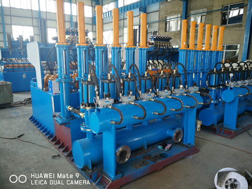 No. 196 6 station tube hydro testing machine
-
 Φ165-Φ235mm ERW tubemill
-
 ET No.171 Used ERW tubemill
-
 NAKATA 2006 used OD355mm ERW tubemill
-
 Used end facing machine
-
 2016 used OD219×(3-8)mm ERW tubemill
-
 2007 used 5-12.5×300×300mm DFT
-
 ERWΦ219 tubemill
-
 200×200×14mm direct forming tubemill
-
 ET No.142 Used 325 ERW tube mill
-
 used 250x250x12mm square direct forming ERW tubemill
-
 used 30×30mm~80×80mm ERW tubemill